Chip-burning device

A chip and adjustment block technology, applied in information storage, static memory, instruments, etc., can solve problems such as low efficiency and unbearable programming personnel, and achieve the effect of reducing finger injuries, improving programming efficiency, and ensuring finger health.

Inactive Publication Date: 2019-01-04
SHENXUN COMP KUNSHAN
View PDF7 Cites 0 Cited by
  • Summary
  • Abstract
  • Description
  • Claims
  • Application Information

AI Technical Summary

Problems solved by technology

Then, in the above-mentioned operation mode, since all are to manually press the pressure block 122 to control the expansion and contraction of some hook parts 121, such an operation mode is not only inefficient, but also the long-time operation will cause the programmer's hands to be unbearable.

Method used


Image

  • Chip-burning device
  • Chip-burning device
  • Chip-burning device

Examples


Embodiment Construction

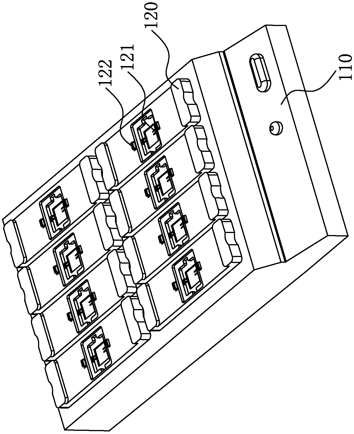
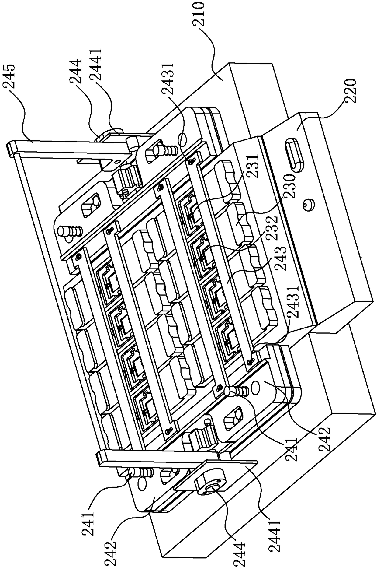
[0026] see image 3 , image 3 A schematic structural diagram of a chip programming device in a preferred embodiment of the present invention is shown.

[0027] In this embodiment, the chip programming device 200 of the present invention is used to quickly and efficiently program the chip 10, saving manpower and material resources and improving the programming efficiency, which includes:

[0028] Base 210, on which a burning disc 220 is fixed;

[0029] Several burning slots 230, which are fixed on the burning disk 220;

[0030] A plurality of hooks 231, which are movably arranged in the plurality of burning grooves 230;

[0031] A plurality of pressing blocks 232 are movably arranged on both sides of the plurality of burning slots 230, and the plurality of pressing blocks 232 control the expansion and contraction of the plurality of hook members 131;

[0032] The pressing mechanism 240 is fixed on the base 210. The pressing mechanism 240 includes: several balance guide pos...


PUM


Abstract

The invention discloses a chip burning device, which comprises a base on which a burning disc is fixed; a plurality of burning grooves fixed on the burning disc; a plurality of clamp hooks are movablyarranged in a plurality of burning grooves; a plurality of pressing blocks movably arranged on both sides of a plurality of burning grooves, the plurality of pressing blocks controlling the expansionand contraction of a plurality of clamping hooks; pressing mechanism, which is fixed on the base, the pressing mechanism comprises a plurality of balance guides, a plurality of balance blocks, a plurality of pressing strips, two adjusting blocks and a movable handle, wherein, the plurality of balance blocks are movably fixed on the plurality of balance guides, the plurality of pressing strips aremovably fixed on the plurality of balance blocks, the two adjusting blocks are fixed on the base, and the movable handle is movably connected with the two adjusting blocks. By using the chip burningand recording device of the invention, the pressing block is pressed down by shaking the movable handle, so that the chip can be taken and placed quickly, the finger injury of the personnel can be reduced, and the finger health of the burning and recording personnel can be ensured.

Description

【Technical field】 [0001] The invention relates to a burning device, in particular to a chip burning device. 【Background technique】 [0002] The burner is a tool for writing data on programmable integrated circuits. The burner is mainly used for programming chips such as single-chip microcomputers or memories. [0003] see figure 1 and figure 2 , figure 1 A structural schematic diagram of a burner is shown, figure 2 A schematic diagram of a partial structure of a programmer is shown. The burner 100 includes: a burner disc 110 , a number of burner slots 120 , a number of hooks 121 and a number of pressing blocks 122 . Wherein, a plurality of burning slots 120 are fixed on the burning disk 110, a plurality of hooks 121 are movably arranged in the plurality of burning slots 120, and a plurality of pressing blocks 122 are movably arranged in the plurality of burning slots 120. The two sides of the plurality of pressing blocks 122 control the expansion and contraction of t...

Claims


Application Information

Patent Timeline
Patent Type & Authority Applications(China)
IPC IPC(8): G11C16/10
CPCG11C16/10
Inventor 贺文辉
Owner SHENXUN COMP KUNSHAN
Why Eureka
Try Eureka