Apparatus and method for dispensing vapocoolants

Inactive Publication Date: 2005-01-04
GEBRAUER
View PDF4 Cites 13 Cited by
  • Summary
  • Abstract
  • Description
  • Claims
  • Application Information

AI Technical Summary

Benefits of technology

The reliability of the container apparatus to provide such fine jet stream flows has been enhanced by filtering of the vapocoolant. More particularly, the container apparatus

Problems solved by technology

As noted above, such was not heretofore possible without the use of an econom

Method used


Image

  • Apparatus and method for dispensing vapocoolants
  • Apparatus and method for dispensing vapocoolants
  • Apparatus and method for dispensing vapocoolants

Examples


Example

DETAILED DESCRIPTION OF THE DRAWINGS

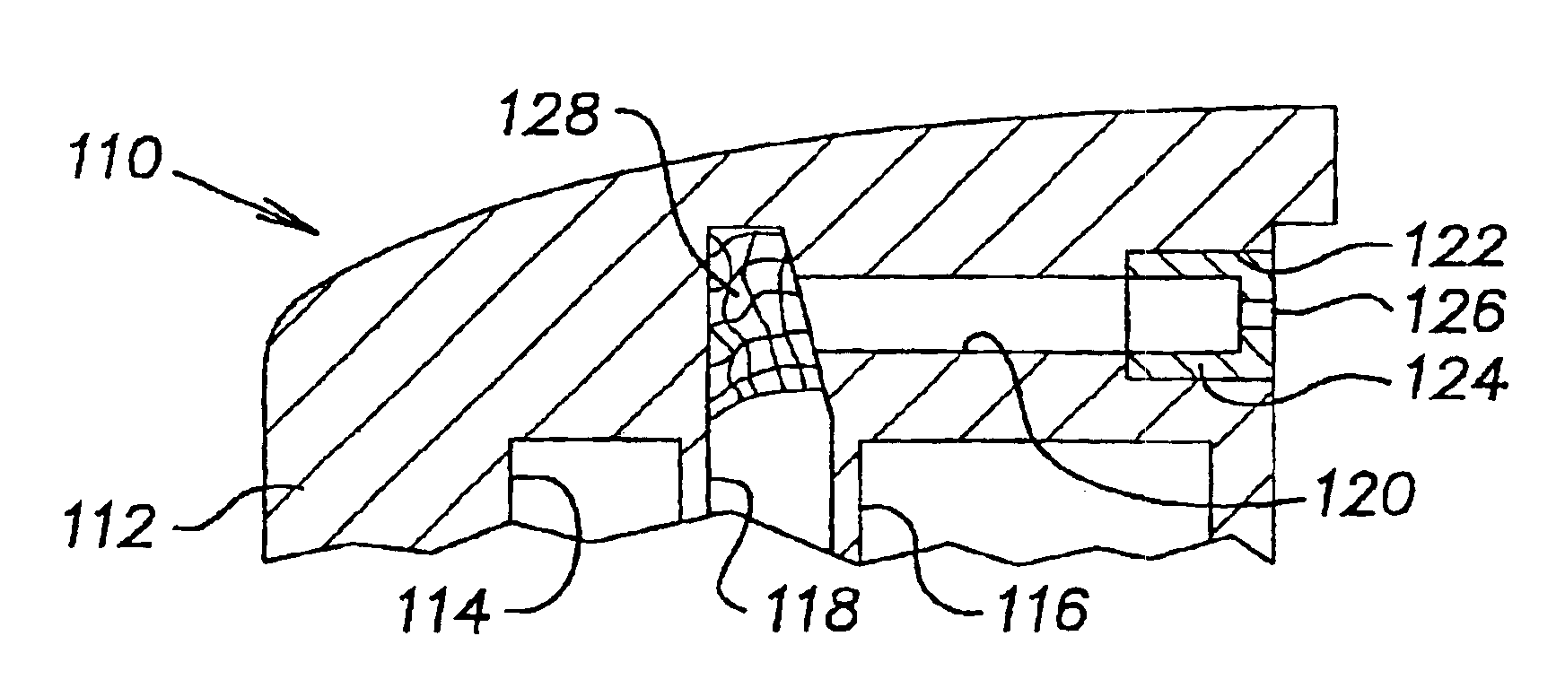
Referring to FIG. 1, a container 10 includes internally mounted co-acting valve apparatus 12 having a dip tube 14. The container 10 comprises a hermetically sealed metal can including an upper mounting cup 16, a side wall 18 and a bottom wall 20. The side wall 18 is secured to the upper cup 16 and bottom wall 20 in a fluid-tight rolled joint.

The interior surfaces of the container 10 may be provided with a protective polymeric coating or film 22. As noted above, a polyamide / polyimide (PAM) resin may be used on aluminum, and an epoxy / phenolic resin may be used on steel, but an unlined container is preferred.

The container 10 is sized to hold about 3.5 ounces of vapocoolant. However, containers may be sized to hold from about 1 ounce to about 10 ounces. The cross-sectional area of the container is selected to assure development of a vapor pressure sufficient to discharge the contents of the container.

The valve apparatus 12 includes a valve body 24 hav...


PUM


Abstract

An apparatus and method for discharging vapocoolants in stream or mist form includes the use of selected fluoroelastomers for valve parts to regulate discharge. The fluoroelastomers provide long-term stability to the vapocoolants to enable superior shelf life without minimal loss or contamination of the vapocoolant. In addition, a filter is provided to remove contaminants from vapocoolant prior to passage through the nozzle opening.

Description

The present invention relates to apparatus and methods for delivery of topical anesthetics and refrigerants, hereinafter collectively referred to as vapocoolants. More particularly, the apparatus comprises containers, associated valve arrangements and, optionally, filters that provide a long shelf life and maintain delivery characteristics over the shelf life in a manner suitable for pharmaceutical applications. The apparatus operates over a range of pressure commonly encountered in medical applications to provide substantially uniform delivery of vapocoolant. The apparatus may be constructed to provide either a stream or a mist delivery.Preferred vapocoolants include ethyl chloride, ethyl chloride-fluorocarbon blends, fluorocarbon fluids and blends of fluorocarbon fluids such as 15% dichlorodifluoromethane and 85% trichloromono-fluoromethane. Also, non-halogen containing low boiling fluids suitable for topical skin application may be used. The vapocoolant will typically operate as ...

Claims


Application Information

Patent Timeline
IPC IPC(8): B65D83/16B65D83/14B67D7/76
CPCB05B15/008B65D83/20B65D83/205B65D83/754B65D83/48B65D83/75B65D83/752B65D83/38B05B15/40
Inventor GROYS, ALEKSANDR
Owner GEBRAUER
Why Eureka
Try Eureka