Spread illuminating apparatus with means for reflecting light dispersely

a technology of illuminating apparatus and light dispersion, which is applied in the direction of lighting and heating apparatus, planar/plate-like light guides, instruments, etc., can solve the problem that the reflected light has an adverse influence on the contrast characteristics of the display devi

Inactive Publication Date: 2005-01-04
MINEBEA CO LTD
View PDF5 Cites 18 Cited by
  • Summary
  • Abstract
  • Description
  • Claims
  • Application Information

AI Technical Summary

Benefits of technology

The present invention has been made in view of the above problems, and it is an object of the present invention to provide a spread illuminating apparatus, in which the light and dark striping of a kind different from the moire pattern is suppressed without increasing the number of components and also without detriment to the usability of light.
In this connection, the same effect can be realized without detriment to other display performance when the pattern is configured such that the maximum angle made by the tangent line to the convex, concave or polygonal surface with respect the datum parallel to the light conductive plate is 3 degrees or smaller
The light dispersive-reflection pattern is formed directly on the light conductive plate without using any additional materials or components, thereby holding down cost increase.

Problems solved by technology

It has been known that this reflected light has an adverse influence on the contrast characteristics of the display device, and the light conductive plate normally has non-reflective coating applied to its lower face for improving contrast.

Method used


Image

  • Spread illuminating apparatus with means for reflecting light dispersely
  • Spread illuminating apparatus with means for reflecting light dispersely
  • Spread illuminating apparatus with means for reflecting light dispersely

Examples


Embodiment Construction

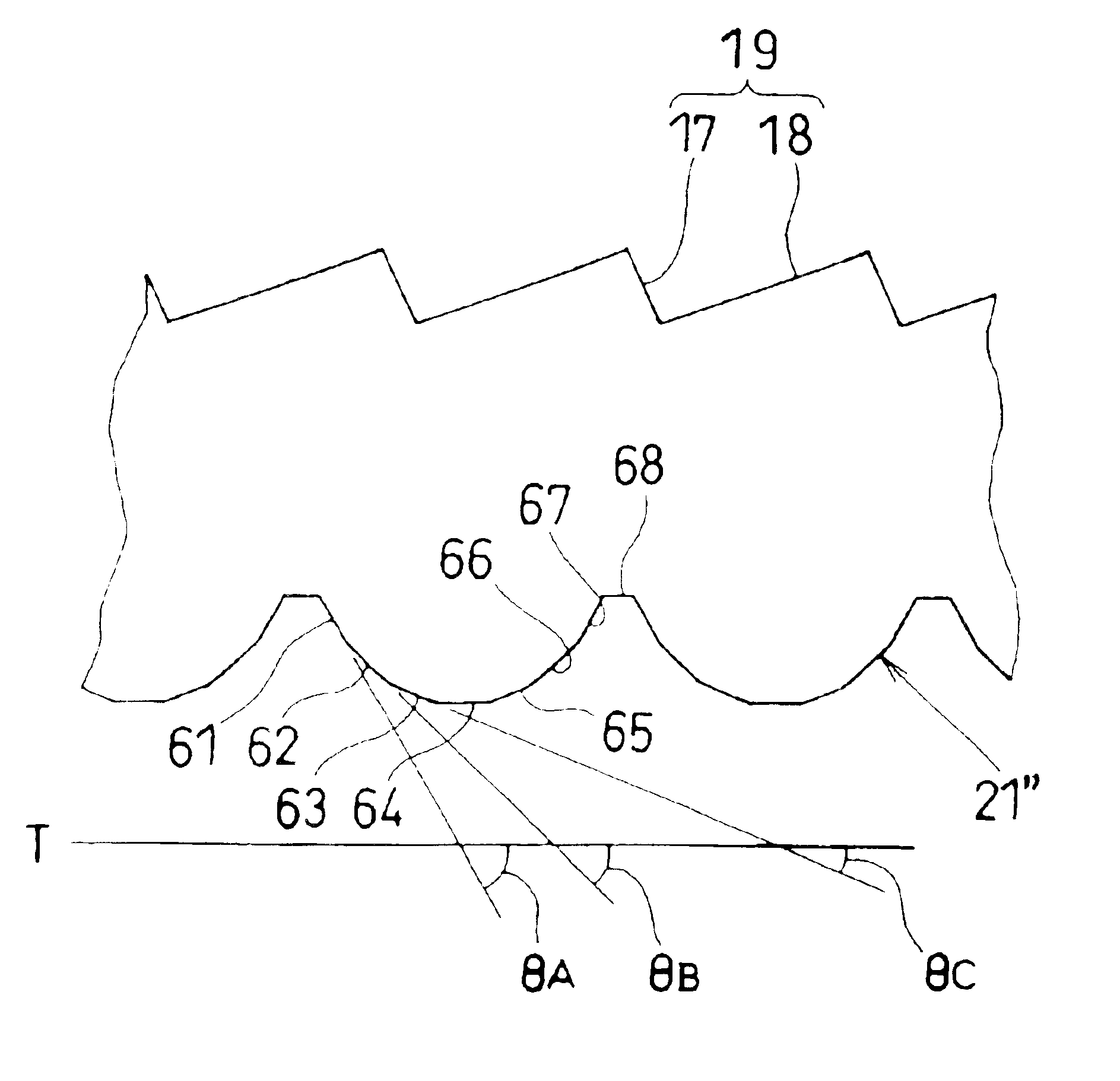
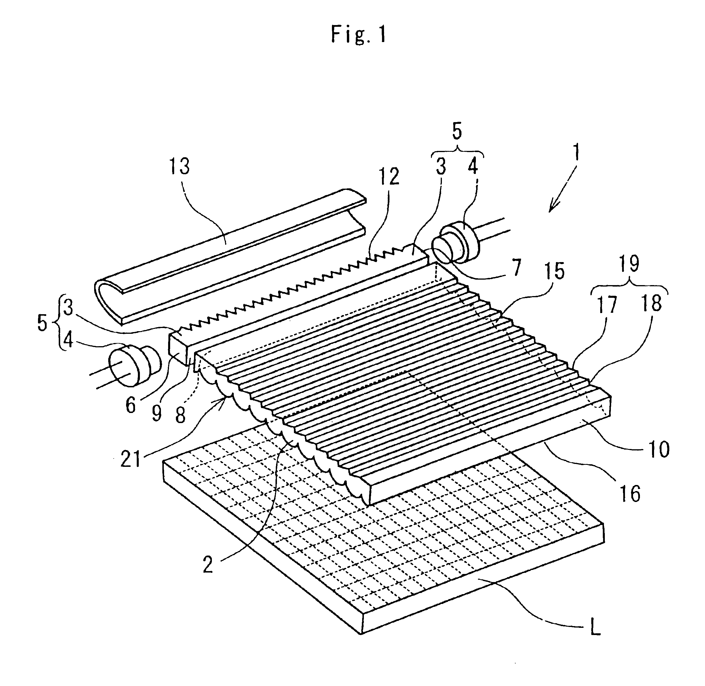
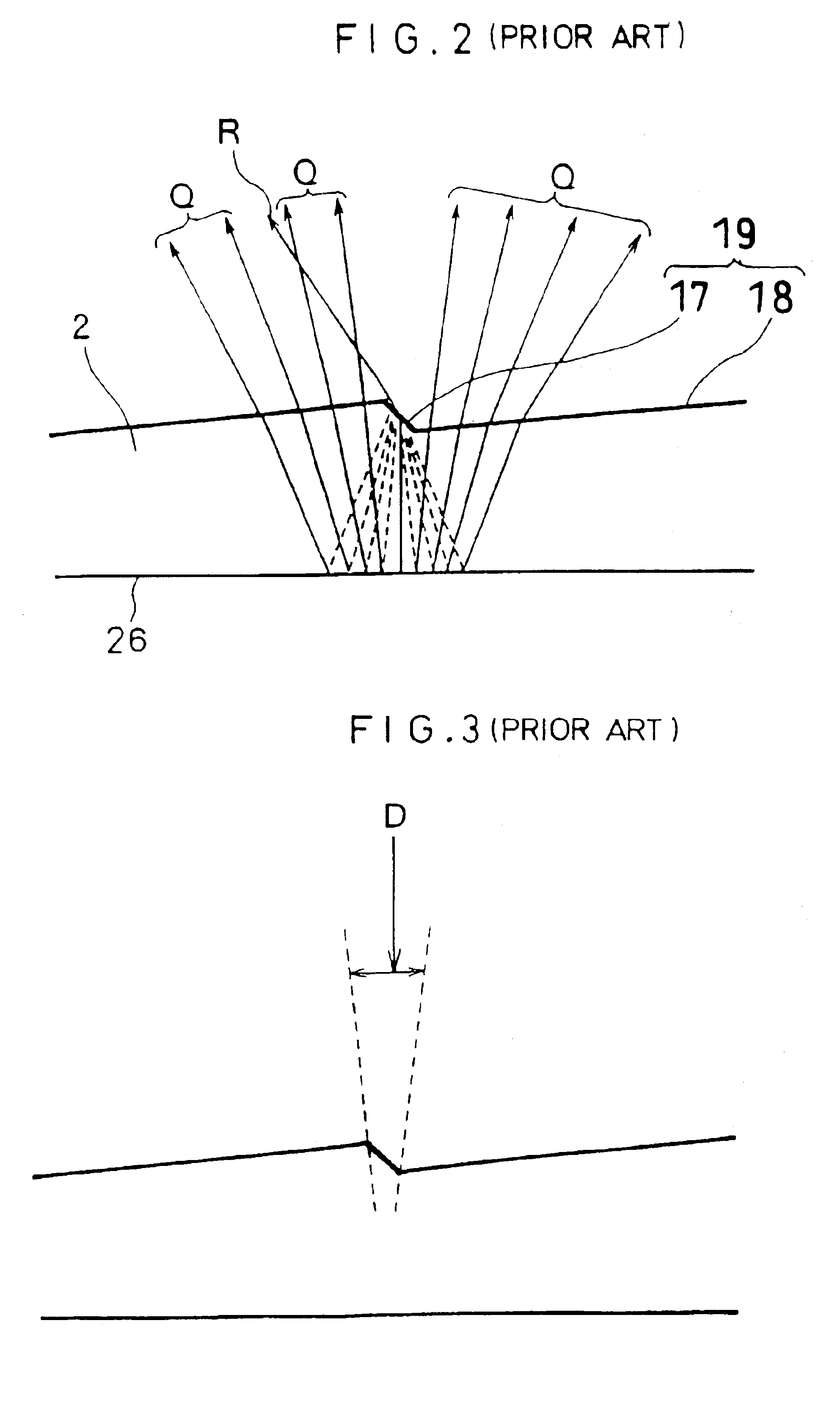
Preferred embodiments of the present invention will be described with reference to the drawings. The spread illuminating apparatus of the present invention is characterized by forming, on the lower face of a light conductive plate of a conventional spread illuminating apparatus, a light dispersive-reflection pattern which is adapted to reflect light in random directions toward a light reflection pattern, and in the construction drawings of the respective embodiments the construction elements corresponding to the elements of the prior art shown in FIG. 13 have the same reference numbers and will not be described in detail.

Referring to FIG. 1, a spread illuminating apparatus 1 generally comprises: a light conductive plate 2; a bar-like lamp 5 disposed along and close to an end face 8 of the light conductive plate 2; and a light reflection member (frame) 13.

The light conductive plate 2 has a light reflection pattern 19 formed on its upper face (observation surface) 15. The light reflec...


PUM


Abstract

A spread illuminating apparatus having a light conductive plate made of a light transmissible material and a bar-like lamp disposed along and close to an end face of the light conductive plate. The spread illuminating apparatus also having a light reflection pattern having a stair-like configuration from a cross-sectional perspective. The light reflection pattern is formed on a major face of the light conductive plate. The spread illuminating apparatus also has a light dispersive-reflection pattern which has, for example, a plurality of convex surfaces which are formed on a major face of the light conductive plate opposite to the major face of the light conductive plate, which is provided with the light reflection pattern.

Description

BACKGROUND OF THE INVENTION1. Field of the InventionThe present invention relates to a spread illuminating apparatus, and more particularly to a spread illuminating apparatus used with a liquid crystal display.2. Description of the Related ArtA liquid crystal display (hereinafter referred to as LCD), which is small in power consumption, low in profile, and light in weight, is heavily used in electric products such as a personal computer (hereinafter referred to as PC), a cellular phone, and the like, and is increasingly demanded.Since a liquid crystal of the LCD does not emit light by itself, the LCD requires an illuminating means to radiate light on the liquid crystal when used in a place where sunlight or interior lighting is not fully available.A PC, particularly notebook-type PC, and a cellular phone are required to be lower in profile and smaller in power consumption, and the requirements are fulfilled by a spread illuminating apparatus of side light type.A conventional spread ...

Claims


Application Information

Patent Timeline
Patent Type & Authority Patents(United States)
IPC IPC(8): F21V8/00
CPCG02B6/0013G02B6/0068G02B6/0038G02B6/0028
Inventor KUNIMOCHI, TORUSUZUKI, SHINGOEGAWA, MOTOJISHIMURA, TAKAHIROOISHI, SHIGEYUKI
Owner MINEBEA CO LTD
Why Eureka
Try Eureka