Connector and cable positioning member of connector

Inactive Publication Date: 2005-01-04
THE FUJIKURA CABLE WORKS LTD
View PDF7 Cites 25 Cited by
  • Summary
  • Abstract
  • Description
  • Claims
  • Application Information

AI Technical Summary

Benefits of technology

With the foregoing problems affecting the related art technology in view, it is an object of the present invention to solve these problems by providing a cable posi

Problems solved by technology

In such structure in which a plurality of outer conductors are collectively connected (also known as a bundle shield structure), it is difficult to maintain a uniform pitch of coaxial cables, especially, central conductors and outer conductors of the coaxial cables.
Problems incurred by this conventional technology are the expenses required for the materials used and the processes required for production.
Further, generally, when the outer conductors are connected together the ground bar is secured in position by solderin

Method used


Image

  • Connector and cable positioning member of connector
  • Connector and cable positioning member of connector
  • Connector and cable positioning member of connector

Examples


Example

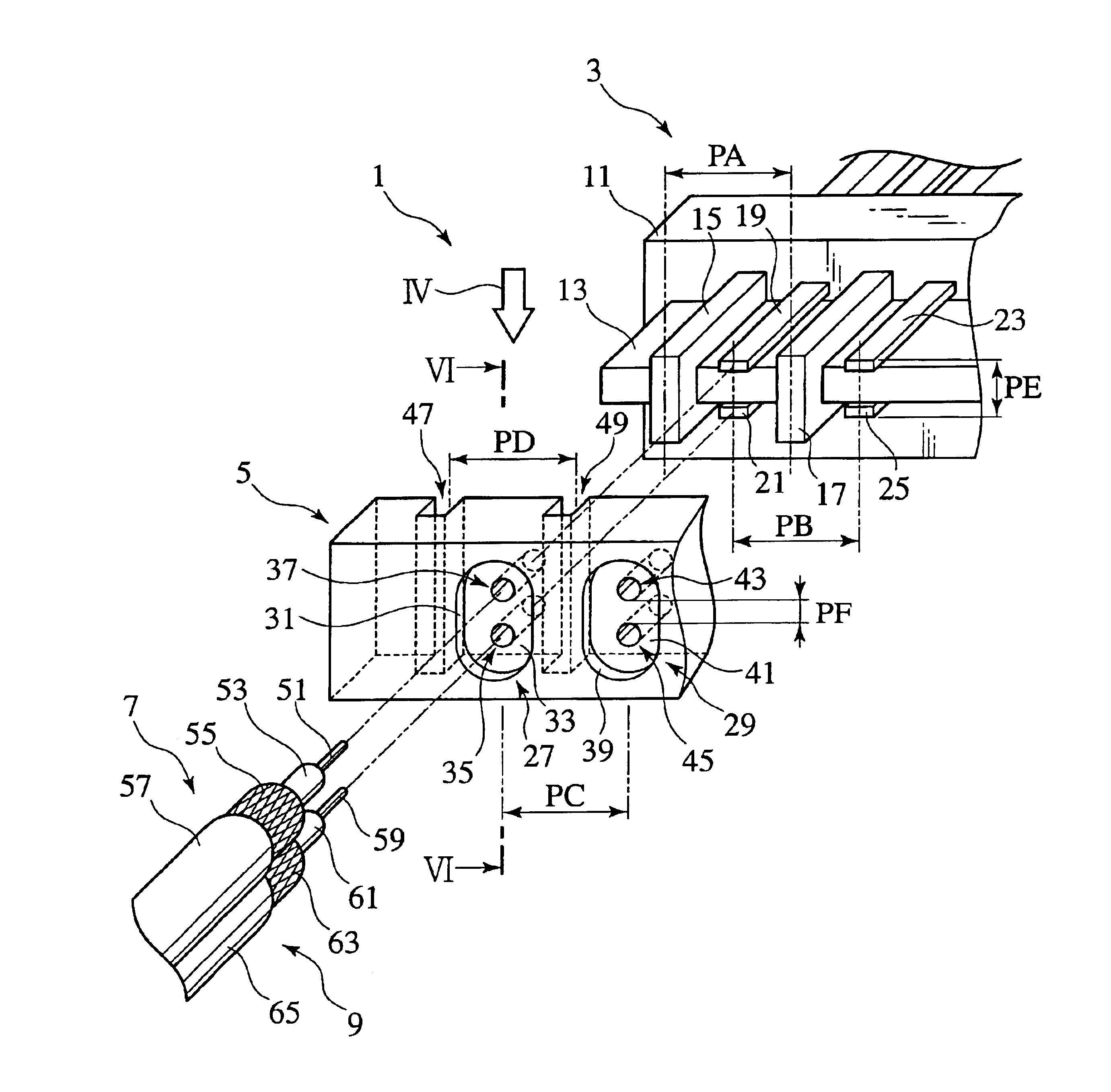
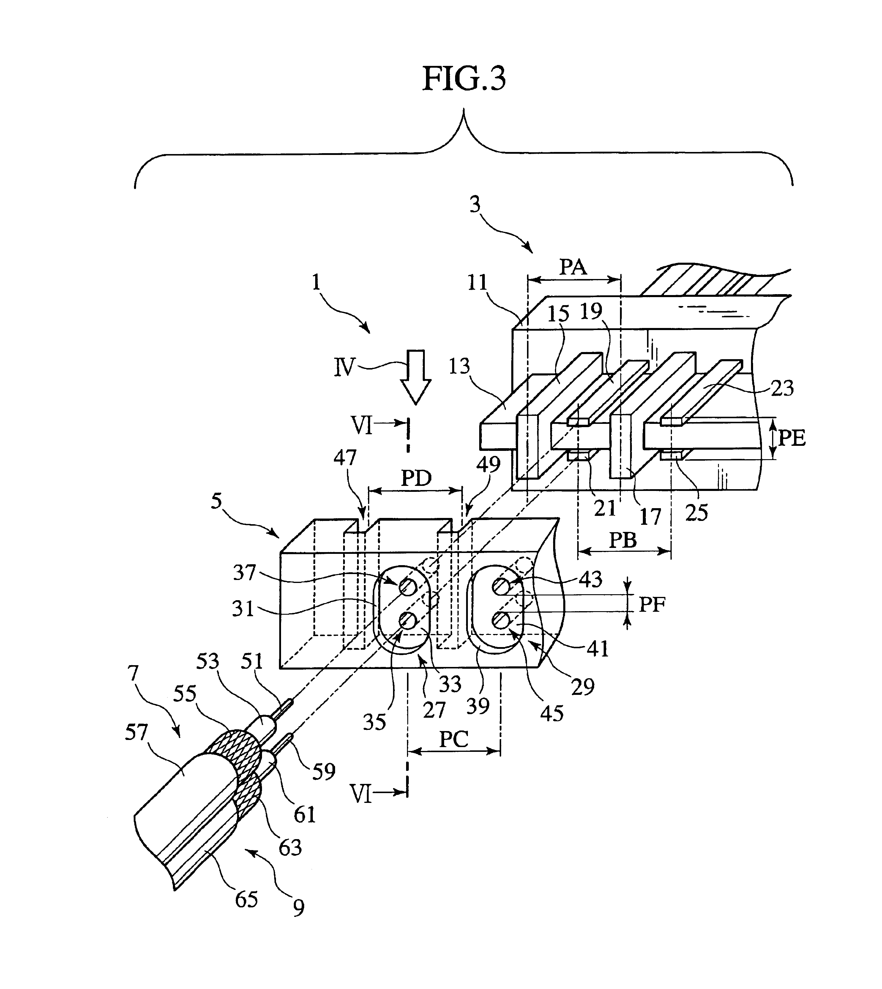
FIG. 3 is an exploded view of a first embodiment of a connector according to this invention. In FIG. 3 the connector 1 includes a connector main body 3, a cable positioning member 5. A plurality of coaxial cables 7 and 9 are connected to the connector main body 3 via the cable positioning member 5.

In this example, a coaxial cable is assumed as the cable connecting to the connector main body, however technology of connecting cables such as a twin coaxial cable or like is within the scope of this invention. Further, the number and arranged positions of the coaxial cables to be connected changes in accordance with the structure of the connector main body, however the structure of the cable positioning member can easily be changed in coordination with the structure of a connector main body, that is to say, the structure of the cable positioning member is not restricted to the structure described herein below.

The connector main body 3 comprises a molded part 11 and a base 13. The base 13...


PUM


Abstract

A connector having a connector main body including a base and a plurality of signal terminals and a plurality of ground terminals both fixed to the base; and a cable positioning member made of conductors for positioning a plurality of cables relative to the connector main body, the cable positioning member including a plurality of securing portions at which the cable positioning member is secured to the ground terminals, and a cable holding portion including a plurality of outer conductor holding portions adapted to hold an outer conductor protruding from the end of each cable and a plurality of insulating layer holding portions adapted to hold an insulating layer protruding from the end of each cable. The cable positioning member is electrically contacted to the ground terminals at the securing portions and to the outer conductors at the outer conductor holding portions.

Description

CROSS-REFERENCE TO RELATED APPLICATIONSThis application is based upon and claims the benefit of priority from Japanese Patent Application No. 2003-72735 filed on Mar. 17, 2003, the entire contents of which are incorporated by reference herein.BACKGROUND OF THE INVENTION1. Field of the InventionThis invention relates to a connector and a cable positioning member of the connector. More specifically, this invention relates to a cable positioning member of a connector used when connecting a cable to the main body of a connector, that enables improved electric properties of the connector through regulating and making uniform the pitch between cables in a plurality of cables as well as a connector that utilizes this cable positioning member.2. Description of Related ArtFIG. 1 shows a method of connecting outer conductors of coaxial cables to each other using a ground bar. In such structure in which a plurality of outer conductors are collectively connected (also known as a bundle shield s...

Claims


Application Information

Patent Timeline
IPC IPC(8): H01R12/16H01R12/00H01R4/02H01R9/05
CPCH01R4/023H01R23/688H01R9/05H01R13/6592
Inventor KUWAHARA, KOICHI
Owner THE FUJIKURA CABLE WORKS LTD
Why Eureka
Try Eureka