

Multiple cylinder internal combustion engine
- Summary
- Abstract
- Description
- Claims
- Application Information
AI Technical Summary
Benefits of technology
Problems solved by technology
Method used
Image

Examples
first embodiment
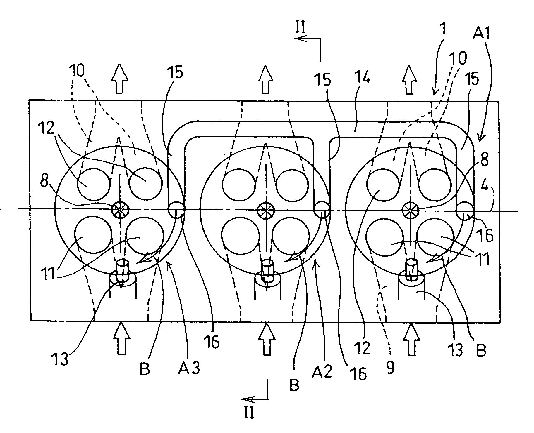
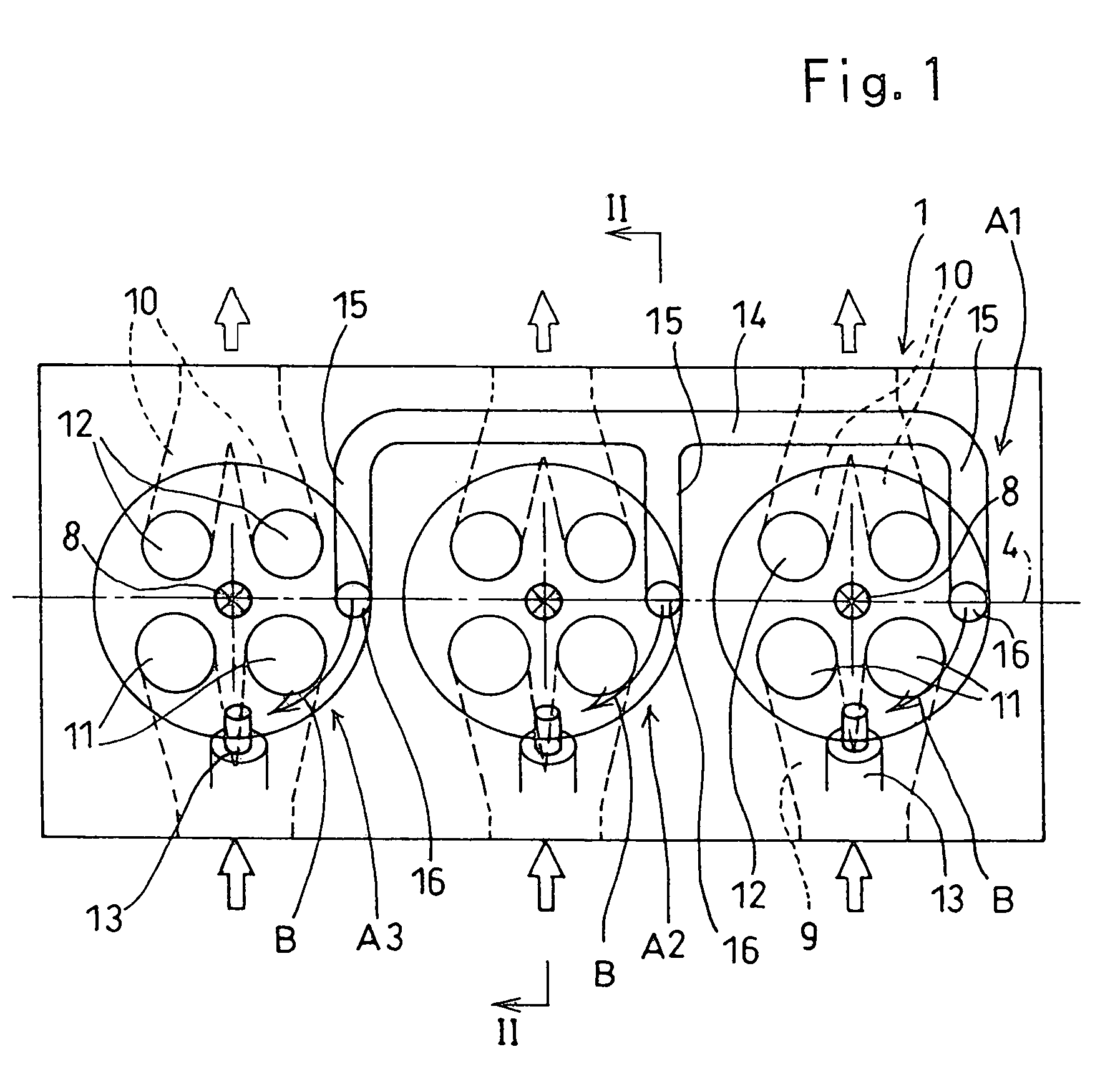
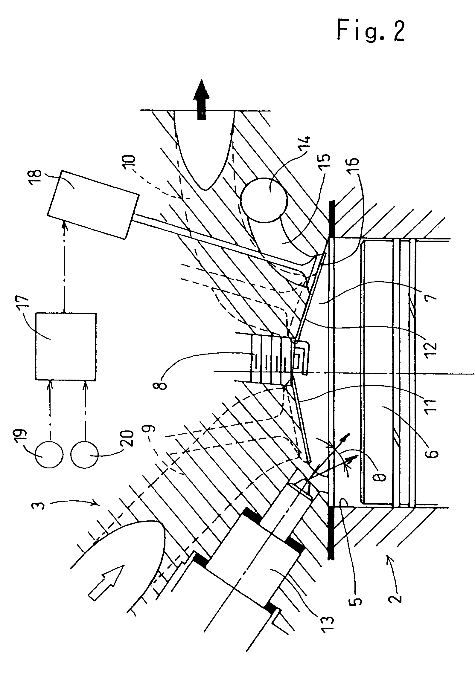
[0043]FIGS. 1–3 illustrate the present invention applied to a conventional in-line three-cylinder four-stroke internal combustion engine.
[0044]The three-cylinder internal-combustion engine 1 comprises a cylinder block 2, a cylinder head 3 secured to an upper surface of the cylinder block. A first cylinder A1, a second cylinder A2 and a third cylinder A3, which share a non-illustrated single crank shaft, are arranged in a row extending along a crank axis 4.
[0045]Each of the three cylinders A1, A2 and A3 is provided with a cylinder bore 5 provided in the cylinder block 2, a piston 6 which moves reciprocally in the cylinder bore 5, a combustion chamber 7 provided as a recess at a lower surface of the cylinder head 3 to open to the cylinder bore 5, a spark plug 8 attached to the cylinder head 3 to face a generally central portion of the combustion chamber 7, two intake ports 9 provided at the cylinder head 3 for opening to the combustion chamber 7, and two exhaust ports 10 provided at t...
second embodiment
[0063]In a second embodiment, unlike the compression ratio of 9–10 in an ordinary four-stroke internal combustion engine burning gasoline, the compression ratio in each-cylinder A1, A2, A3 is set to such a high value of about 15–18 as may lead to abnormal combustion such as knocking during high-load operation. Further, the open / close valves 16 of the cylinders A1, A2 and A3 are operated by the electrical opening / closing means such as a magnetic coil 17 which in turn is controlled by a control circuit 21 into which signals from a load sensor 19 and a crank angle sensor 20 are inputted in accordance with e.g. the open degree of a throttle valve. With this arrangement, the cylinder valves, in a high-load operation mode, are opened at an earlier stage of the explosion (expansion) stroke of the cylinders A1, A2, A3 and at a later stage of the suction stroke, the opening of the valves being implemented at the same crank angle and at the same time, and continued for a predetermined period ...
third embodiment
[0069]FIGS. 5 and 6 illustrate the present invention applied to a conventional four-stroke, four-cylinder internal combustion engine.
[0070]The four-cylinder internal combustion engine 1′ comprises a first cylinder A1′, a second cylinder A2′, a third cylinder A3′ and a fourth cylinder A4′ which share a non-illustrated single crank shaft and which are arranged in a row extending along a crank axis 4′.
[0071]As in the first embodiment each of the cylinders A1′, A2′ A3′ and A4′ is provided with a cylinder bore, a piston, a combustion chamber, a spark plug, intake ports with intake valves, exhaust ports with exhaust valves, a fuel injection valve.
[0072]As seen from the stroke chart shown in FIG. 6, ignition for the cylinders A1′, A2′, A3′ and A4′ of the four-cylinder internal combustion engine 1′ is performed in the order of the first cylinder A1′, the third cylinder A3′, the fourth cylinder A4′, and then the second cylinder A2′.
[0073]A single common communication path 14′ is provided whi...
PUM
 Abstract
Description
Claims
Application Information