Method of making tear-resistant adhesive/combination bond pattern

a bonding pattern and adhesive technology, applied in the field of bonding composites, can solve the problems of prone to fracture at the bonding location under, affecting the bonding effect, etc., and achieve the effect of dissolving the stress

Inactive Publication Date: 2005-01-04
KIMBERLY-CLARK WORLDWIDE INC
View PDF17 Cites 37 Cited by
  • Summary
  • Abstract
  • Description
  • Claims
  • Application Information

AI Technical Summary

Benefits of technology

In some embodiments, the bond pattern comprises, as ones of the bond elements, a first sub-array of longitudinally-oriented separate, distinct, and spaced stress receptor elements disposed along the length, and proximate the side edges of, the bond pattern. In such embodiments, the bond pattern can also comprise, as ones of the bond elements, a second sub-array of longitudinally-oriented separate, distinct, and spaced transfer and dissipation elements spaced along the length of the bond pattern, typically inwardly of the side edges of the bond pattern and generally inwardly of the stress receptor elements. Respective ones of the transfer and dissipation elements can have first ends disposed toward an interior of the bond pattern. The respective transfer and dissipation elements can extend to second ends adjacent the side edges of the bond pattern between respective ones of the stress receptor elements. The stress transfer and dissipation elements can direct stresses inwardly into the interior of the bond pattern, and can dissipate such stresses on the interior of the bond pattern.
The adherent material can be distributed and / or dispersed between the first and second thin-section elements as a result of the force being applied to the thin-section elements, such distribution and / or dispersal of the adherent material assisting in defining outer transverse edges of the adherent material in the bond pattern.
In a second family of embodiments, the invention comprehends a bond pattern, reflecting application of force, which urges the first and second thin-section elements toward each other in face-to-face relationship to form an array of separate, distinct, and spaced elongate bond elements affixing the first and second thin-section elements to each other. Bonds corresponding to the bond elements are activated by a combined application of adherent material, pressure, and one of thermal energy or ultrasonic-frequency energy to at least one of the first and second thin-section elements. The adherent material is one or both distributed and dispersed between the first and second thin-section elements as a result of the force being applied to the thin-section elements. One or both of the distribution and dispersal of the adherent material assist in defining outer transverse edges of the adherent material in the bond pattern.
As ones of the bond elements, a first sub-array of longitudinally-oriented separate, distinct, and spaced stress receptor elements is disposed along the length, and proximate the side edges of, the bond pattern. A second sub-array of longitudinally-oriented separate, distinct, and spaced transfer and dissipation elements is spaced along the length of the bond pattern, preferably inwardly of the side edges of the bond pattern and preferably generally inwardly of the stress receptor elements. Respective transfer and dissipation elements have first ends disposed toward an interior of the bond pattern, and which extend to second ends adjacent the side edges of the bond pattern between respective ones of the stress receptor elements. The stress transfer and dissipation elements direct stresses inwardly into the interior of the bond pattern, and assist in dissipating such stresses on the interior of the bond pattern.
In some embodiments, respective transfer and dissipation elements have first ends disposed toward an interior portion of the bond pattern, and extending to second ends adjacent the side edges of the bond pattern between respective ones of the stress receptor elements. In such embodiments, the transfer and dissipation elements direct stresses inwardly to the interior portion of the bond pattern, and assist in dissipating such stresses at the interior portion of the bond pattern.

Problems solved by technology

In absorbent articles, the portions of the article where different layers or components are bonded to each other tend to incur significant stress concentrations, and in absorbent articles using conventional bond patterns, tend to fracture at those bonded locations under such stresses.

Method used


Image

  • Method of making tear-resistant adhesive/combination bond pattern
  • Method of making tear-resistant adhesive/combination bond pattern
  • Method of making tear-resistant adhesive/combination bond pattern

Examples


Embodiment Construction

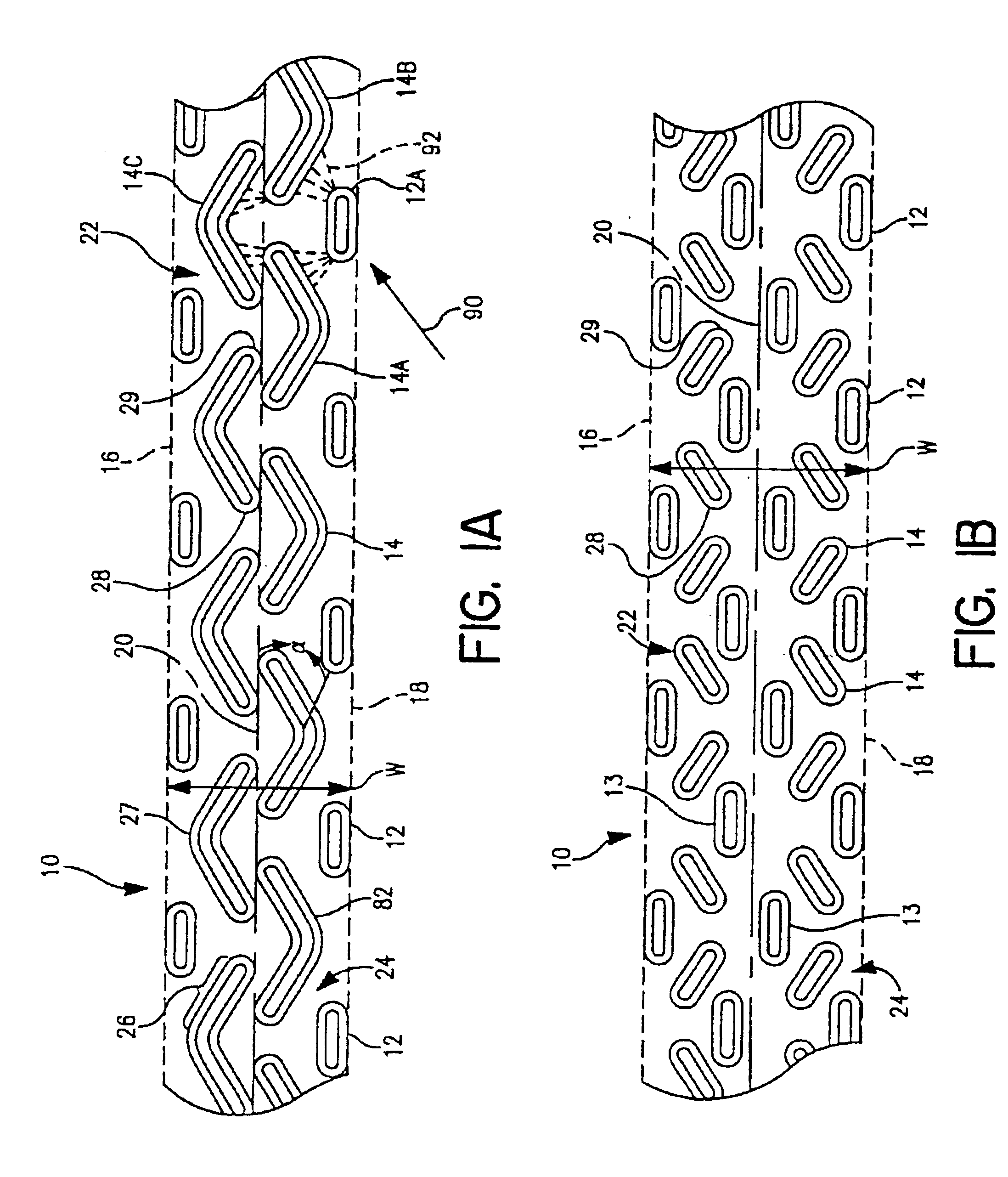
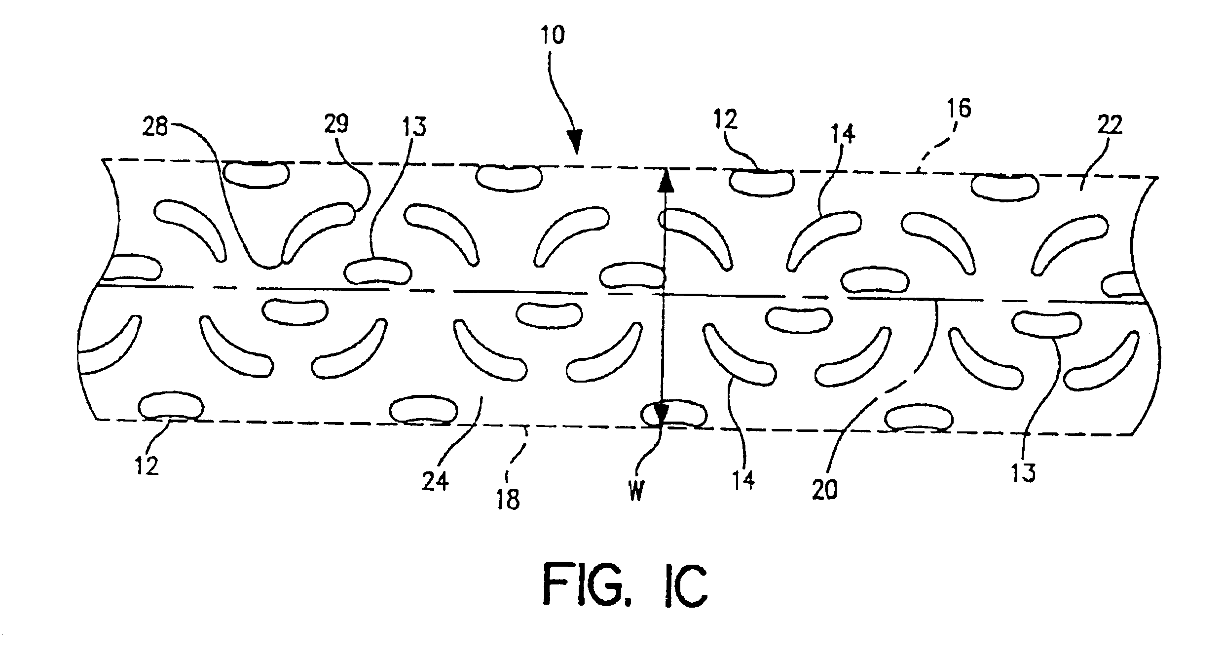
FIGS. 1A and 1B show preferable embodiments of bond pattern 10 of the invention, which is described more fully in application Ser. No. 09 / 651,042 filed Aug. 30, 2000, of common assignment herewith, and which is herein incorporated by reference in its entirety. Bond pattern 10 has a first side edge 16, a second side edge 18, and a central longitudinal axis 20 which divides the bond pattern 10, as defined by the bond elements, into a first opposing pattern combination 22 on a first side of axis 20 and a second opposing pattern combination 24 on an opposing second side of axis 20. Bond pattern 10 has a pattern length defined in terms of distance measured along central longitudinal axis 20, and a pattern width “W” represented by distance between first side edge 16 and second side edge 18 of bond pattern 10. Correspondingly, the overall area of bond pattern 10 is defined as the area which participates in absorbing and dissipating, by operation of bond pattern 10, stresses received into t...


PUM

PropertyMeasurementUnit
anglesaaaaaaaaaa
anglesaaaaaaaaaa
anglesaaaaaaaaaa

Abstract

Bonded composites, absorbent articles comprising such bonded composites, and processes for bonding thin-section elements. The bonded composite has first and second thin-section elements bonded to each other, at least in part by bond elements and at least in part by adherent material. The adherent material is disposed between the first and second thin-section elements proximate and about the bond elements. The adherent material, at least in part, bonds the thin-section elements to each other at loci of the adherent material. The bond patterns are arranged and configured to preferentially direct stresses imposed on the bond pattern, inwardly into the interior of the bond pattern for distribution, dissipation, and termination.

Description

BACKGROUNDThe present invention relates to a bonded composite of a first thin-section element of sheet material and a second thin-section element bonded together by a bond pattern. More particularly, one of the contemplated applications for the present invention is in bonding outer cover and body side liner thin-section elements of absorbent articles to one another.Absorbent articles have been known for a long time as personal care hygiene products. Absorbent articles find use, for example, as diapers, training pants, incontinence products, women's sanitary pads, and the like. Such absorbent articles are designed and constructed to absorb and store liquid bodily excretions such as urine, menstrual fluid, or blood. Women's sanitary pads are used, for example, to absorb the liquids excreted prior to, during, and after menstruation.In absorbent articles, the portions of the article where different layers or components are bonded to each other tend to incur significant stress concentrat...

Claims


Application Information

Patent Timeline
Patent Type & Authority Patents(United States)
IPC IPC(8): A61F13/15B32B5/26B32B5/22D04H13/00A61F13/496A61F5/44A61F13/49A61F13/511A61F13/514A61F13/515B32B7/14
CPCA61F13/15756A61F13/496A61F13/515B32B5/26D04H13/003D04H13/007D04H13/002A61F2013/51078Y10T428/24851Y10T428/24793Y10T428/24826A61F13/4963D04H1/559A61F13/15
Inventor MALCHOW, GREGORY LYNNHOO, DANIELBLENKE, TIMOTHY JAMESRADKE, JEFFRY JON
Owner KIMBERLY-CLARK WORLDWIDE INC
Why Eureka
Try Eureka