Liquid crystal display with display regions of light reflection mode and light transmission mode

a liquid crystal display and light reflection technology, applied in static indicating devices, non-linear optics, instruments, etc., can solve the problems of increasing the manufacturing cost of the liquid crystal display, the image displayed in a dark place can be scarcely recognized, and the use environment of reflection type liquid crystal display is limited, so as to achieve suppressing power consumption and high visible image

Inactive Publication Date: 2005-01-04
JAPAN DISPLAY CENTRAL CO LTD
View PDF2 Cites 4 Cited by
  • Summary
  • Abstract
  • Description
  • Claims
  • Application Information

AI Technical Summary

Benefits of technology

An object of the present invention is to provide a liquid crystal display capable of displaying a highly visible image without depending on the environment of use and also capable of further suppressing the power consumption.

Problems solved by technology

However, a light source is not included in the reflection type liquid crystal display, with the result that the image displayed in a dark place can be scarcely recognized.
In other words, the reflection type liquid crystal display is limited by the environment of use.
However, the light reflecting conductive film and the light transmitting conductive film, which are included in the particular liquid crystal display, are formed by independent processes so as to lower the yield and to increase the manufacturing cost of the liquid crystal display.
In addition, it is necessary to superpose the light reflecting conductive film and the light transmitting conductive film one upon the other in the liquid crystal display of the particular construction, with the result that a marked reduction in reflectance is derived from the overlapping of these conductive films so as to make it difficult to obtain a bright image.
Further, in the liquid crystal display utilizing the light reflection mode and the light transmission mode in combination, while certainly low in its power consumption compared with the liquid crystal display of the light transmission mode, the power consumption is not necessarily lowered sufficiently.

Method used


Image

  • Liquid crystal display with display regions of light reflection mode and light transmission mode
  • Liquid crystal display with display regions of light reflection mode and light transmission mode
  • Liquid crystal display with display regions of light reflection mode and light transmission mode

Examples


Embodiment Construction

Some embodiments of the present invention will now be described in detail with reference to the accompanying drawings. In the accompanying drawings, the same constituting elements are denoted by the same reference numerals so as to avoid an overlapping description.

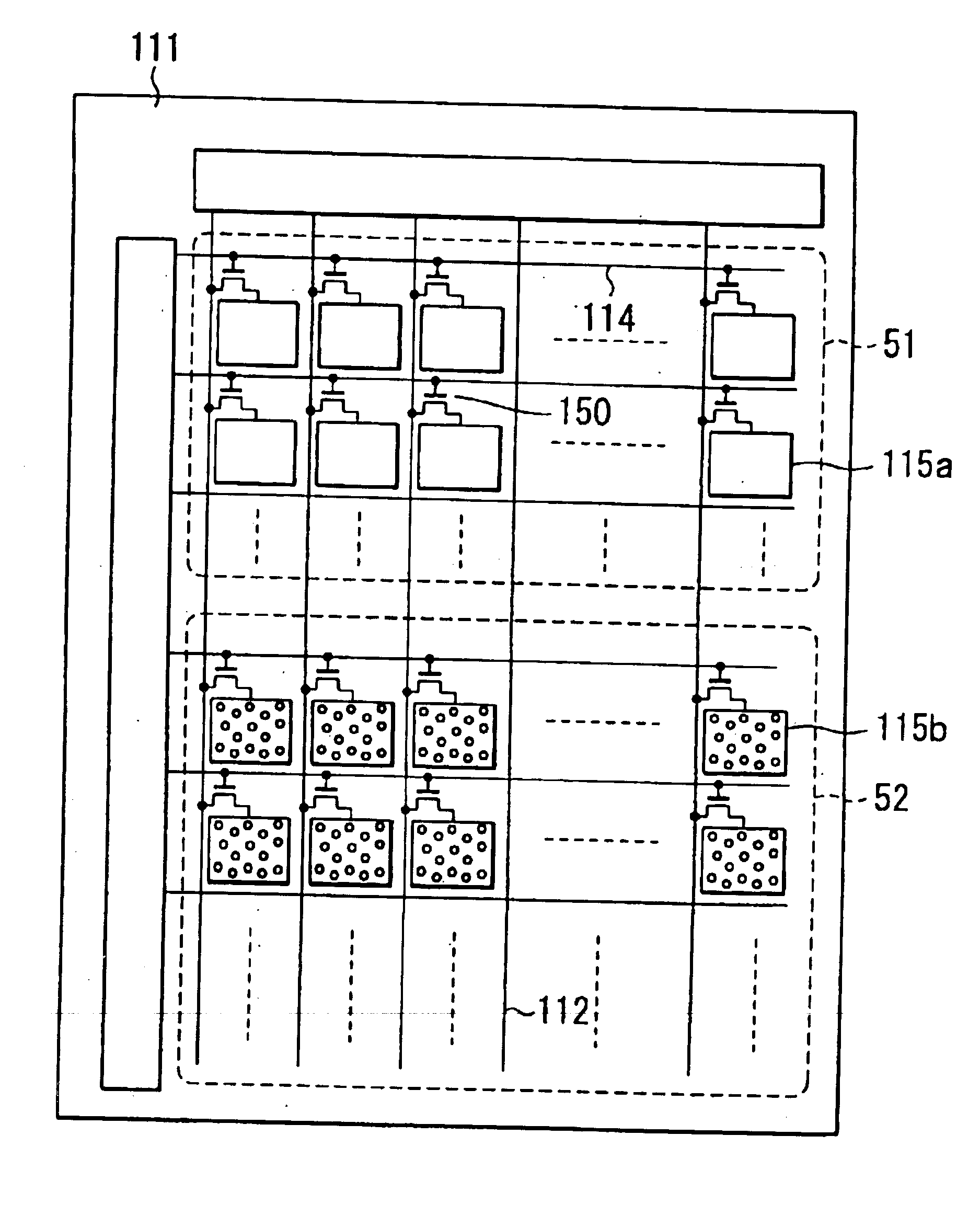
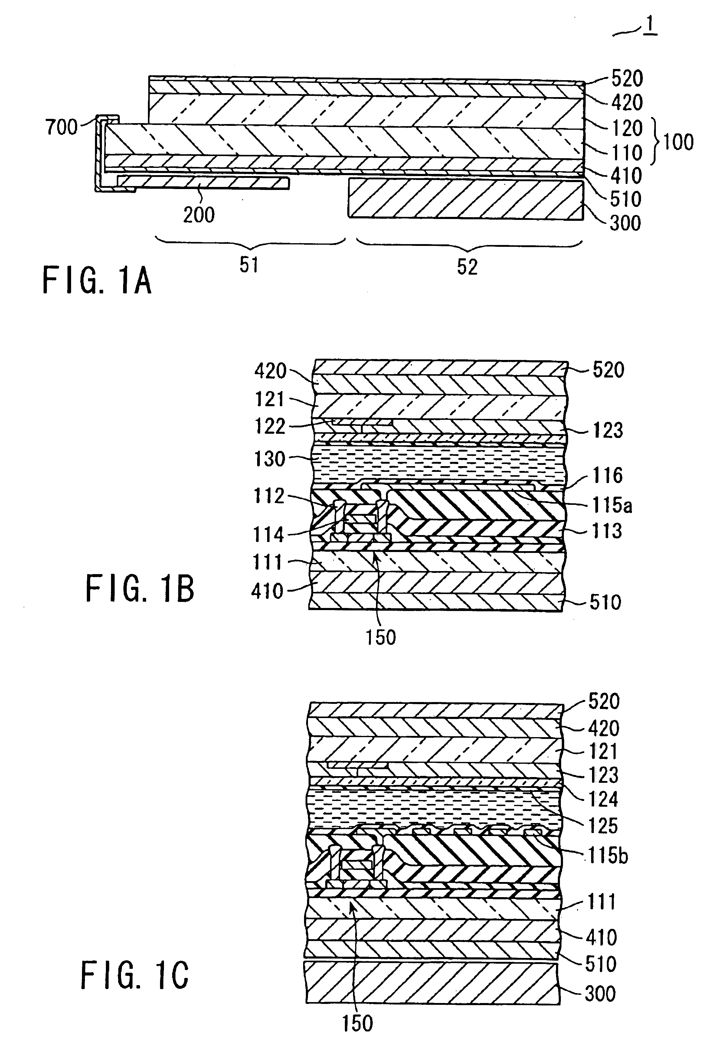
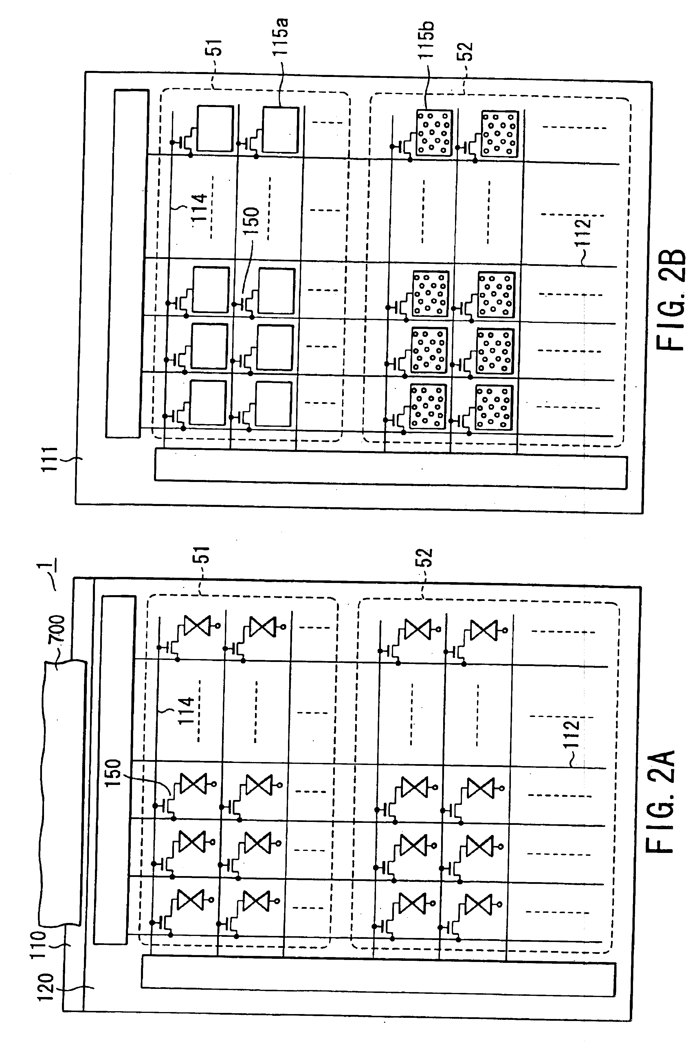
FIG. 1A is a cross-sectional view schematically showing the construction of a liquid crystal display 1 according to a first embodiment of the present invention, and FIGS. 1B and 1C are cross-sectional views each showing in a magnified fashion a part of the liquid crystal display 1 shown in FIG. 1A. Also, FIG. 2A is a plan view showing the liquid crystal display 1 shown in FIG. 1A, and FIG. 2B is a plan view schematically showing the array substrate included in the liquid crystal display 1 shown in FIG. 1A.

The liquid crystal display 1 according to the first embodiment of the present invention is, for example, a VGA type liquid crystal display having a diagonal dimension of 10 cm. In the liquid crystal display 1, the display...


PUM

PropertyMeasurementUnit
diameteraaaaaaaaaa
diameteraaaaaaaaaa
diameteraaaaaaaaaa

Abstract

There is provided a liquid crystal display wherein a first display region corresponding to a first area on which first pixel electrodes are provided displays an image by light reflection mode, and a second display region corresponding to a second area on which second pixel electrodes are provided can display an image by light transmission mode.

Description

BACKGROUND OF THE INVENTION1. Field of the InventionThe present invention relates to a liquid crystal display capable of displaying an image by a light reflection mode and a light transmission mode.2. Description of the Related ArtIt was sufficient for the conventional display of portable equipment such as a portable telephone or a pager to be capable of displaying simple characters such as numerals and letters. However, in accordance with the drastic development in the IT technologies achieved in recent years, it is desirable for a small, light and thin display having a low power consumption and capable of displaying a high quality color image to be put to a practical use even in the field of portable equipment, particularly, a portable information terminal.As a display meeting the requirement noted above, a reflection type liquid crystal display, for example, is considered hopeful and has already been put partly to a practical use. When used outdoors in the daytime, the reflection...

Claims


Application Information

Patent Timeline
Patent Type & Authority Patents(United States)
IPC IPC(8): G02F1/1335G02F1/13G02F1/13363
CPCG02F1/133553G02F1/133555G02F2001/133638G02F1/133638G02F1/1335
Inventor SEIKI, MASAHIROWATANABE, RYOICHITOYAMA, AKIMASA
Owner JAPAN DISPLAY CENTRAL CO LTD
Why Eureka
Try Eureka