Image display
a liquid crystal display and image technology, applied in static indicating devices, non-linear optics, instruments, etc., can solve the problems of low visibility, degradation of visibility in reflective displays, and difficulty in creating a suitable optical design for reflective display units and transmissive display units
- Summary
- Abstract
- Description
- Claims
- Application Information
AI Technical Summary
Benefits of technology
Problems solved by technology
Method used
Image

Examples
first embodiment
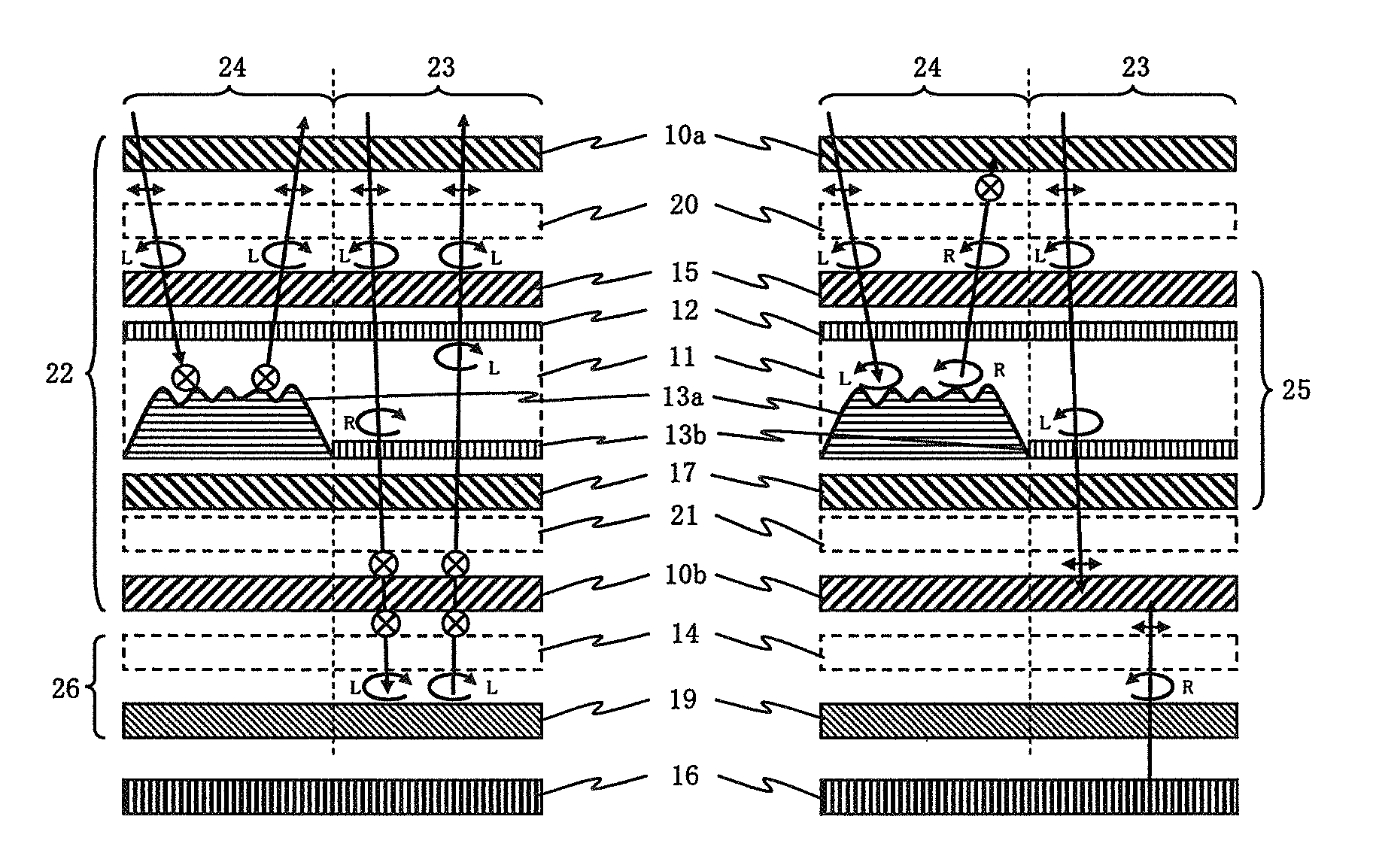
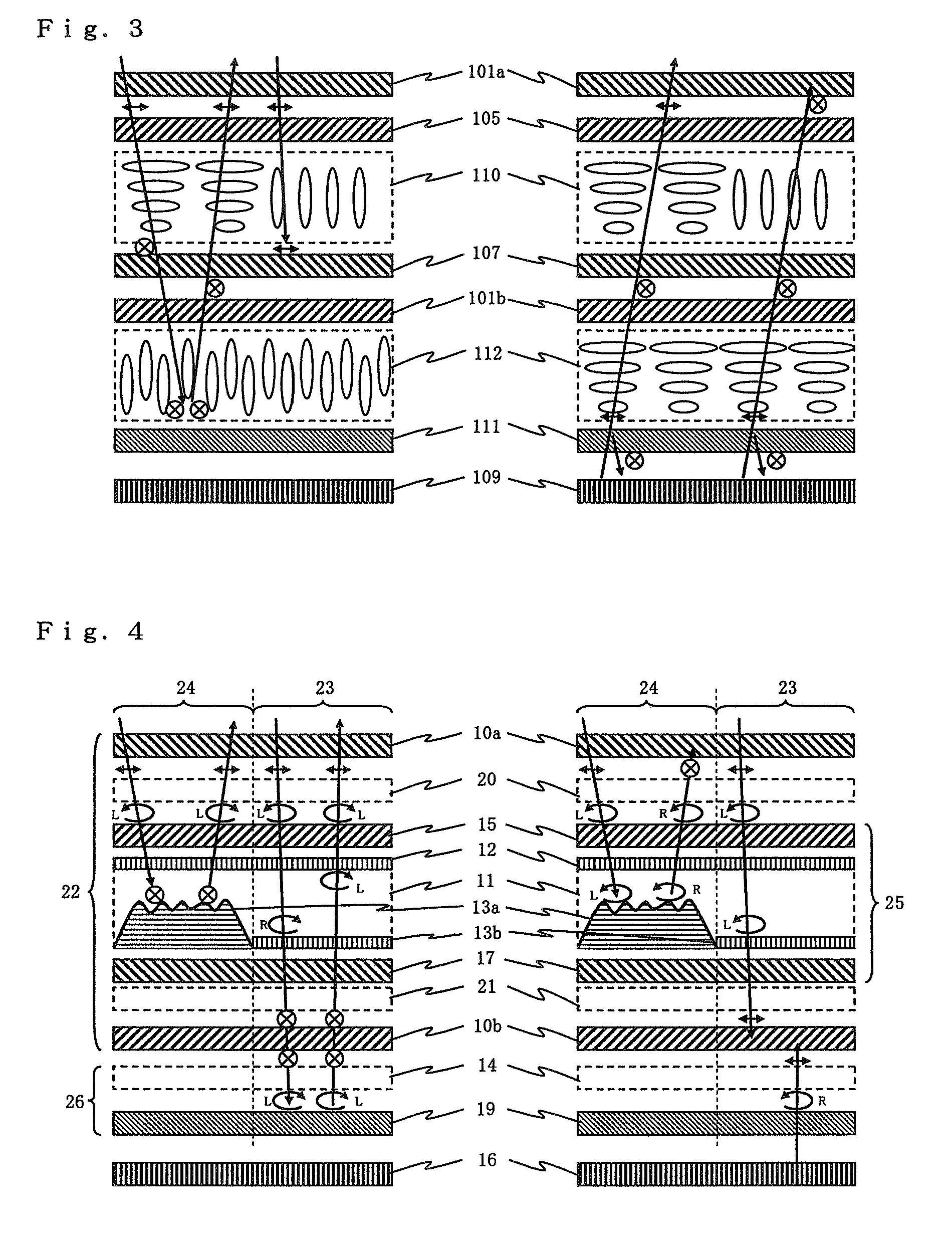
[0050]Referring to FIGS. 4 and 5, a liquid crystal display element according to a first embodiment is illustrated, where reflection control element 26 and liquid crystal display layer 22 are laminated in this order above back light source 16.
[0051]Back light source 16 may be any light source as long as it can illuminate liquid crystal display layer 22 from the back, such as a side-light type back light which includes a light source disposed on a side surface, a directly-underneath type back light which includes a light source disposed directly underneath an liquid crystal display element, an organic electroluminescent device, an inorganic electroluminescent device, and the like. Here, the side-light and directly-underneath type back light sources may include a cold cathode ray tube, white LED, LEDs of three primary colors, and the like. Preferably, back light source 16 can be manually or automatically controlled to irradiate an appropriate amount of light.
[0052]Reflection control el...
second embodiment
[0119]A second embodiment differs from the first embodiment in that reflection control element 60 comprises reflective layer 61 which is made of an alignment type holographic polymer dispersion liquid crystal (PDLC), which Bragg reflects linearly polarized light whose reflectivity can be controlled by a voltage applied thereto, as illustrated in FIGS. 10 and 11. The configuration in this embodiment except for the foregoing is the same as the first embodiment.
[0120]Referring to FIGS. 12(a) and 12(b), reflective layer 61 shown in FIGS. 10 and 11 is illustrated, where reflective layer 61 comprises transparent substrate 30, transparent electrode 31, and liquid crystal layer 33 made up of an alternate lamination of liquid crystal and polymerized liquid crystal monomer. This reflective layer 61 receives incident light 34 such as linearly polarized light 35 in the left-to-right direction on the surface of the drawing sheet and linearly polarized light 35 in a direction perpendicular to the...
third embodiment
[0130]A third embodiment differs from the first and second embodiments in that the third embodiment employs reflection control element 62 which comprises a laminate of phase control layer 63 capable of controlling the phase with a voltage applied thereto, and reflective layer 64 for reflecting certain linearly polarized light and transmitting linearly polarized light orthogonal thereto, as illustrated in FIGS. 14 and 15.
[0131]The configuration in this embodiment except for the foregoing is the same as that in the first and second embodiments.
[0132]Referring to FIG. 16, phase control layer 63 shown in FIGS. 14 and 15 is illustrated, where phase control layer 63 comprises transparent substrate 30, transparent electrode 31, and liquid crystal layer 43. As illustrated in FIG. 16, phase control layer 63 comprises homogeneously aligned liquid crystal layer 43 sandwiched between transparent substrates 31 each formed with transparent electrode 30. Retardation (birefringence phase difference...
PUM
| Property | Measurement | Unit |
|---|---|---|
| refractive index | aaaaa | aaaaa |
| refractive index | aaaaa | aaaaa |
| voltages | aaaaa | aaaaa |
Abstract
Description
Claims
Application Information
 - R&D
- Intellectual Property
- Life Sciences
- Materials
- Tech Scout
- Unparalleled Data Quality
- Higher Quality Content
- 60% Fewer Hallucinations
Browse by: Latest US Patents, China's latest patents, Technical Efficacy Thesaurus, Application Domain, Technology Topic, Popular Technical Reports.
© 2025 PatSnap. All rights reserved.Legal|Privacy policy|Modern Slavery Act Transparency Statement|Sitemap|About US| Contact US: help@patsnap.com