Electronics rack assemblies and associated components

a rack and rack assembly technology, applied in the field of rackmounted servers, can solve the problems of unsightly cables, potentially dangerous states of disarray, and time-consuming operation, and achieve the effects of avoiding re-installation, avoiding re-installation, and avoiding re-installation

Inactive Publication Date: 2005-01-04
INTEL CORP
View PDF16 Cites 51 Cited by
  • Summary
  • Abstract
  • Description
  • Claims
  • Application Information

AI Technical Summary

Problems solved by technology

This is a time-consuming operation with respect to relatively expensive equipment that is normally expected to operate with a minimum of down-time.
Many known server racks include dozens of cables in unsightly, disorganized, and potentially dangerous states of disarray.
When a prior art e-tray is removed from a server rack, the service person may neglect to first power-own the e-tray.
This can result in harmful arcing across the terminals of power supply connectors, to the extent that the terminals are often fused and will need to be replaced, thus incurring even more time and effort before the e-tray can be reinserted into the server rack.
In addition, the service person can be exposed to potentially hazardous conditions.

Method used


Image

  • Electronics rack assemblies and associated components
  • Electronics rack assemblies and associated components
  • Electronics rack assemblies and associated components

Examples


Embodiment Construction

In the following detailed description of embodiments of the invention, reference is made to the accompanying drawings which form a part hereof, and in which is shown by way of illustration specific preferred embodiments in which the disclosure may be practiced. These embodiments are described in sufficient detail to enable those skilled in the art to practice them, and it is to be understood that other embodiments may be utilized and that mechanical, compositional, structural, electrical, and procedural changes may be made without departing from the spirit and scope of the present disclosure. The following detailed description is, therefore, not to be taken in a limiting sense, and the scope of embodiments of the present invention is defined only by the appended claims.

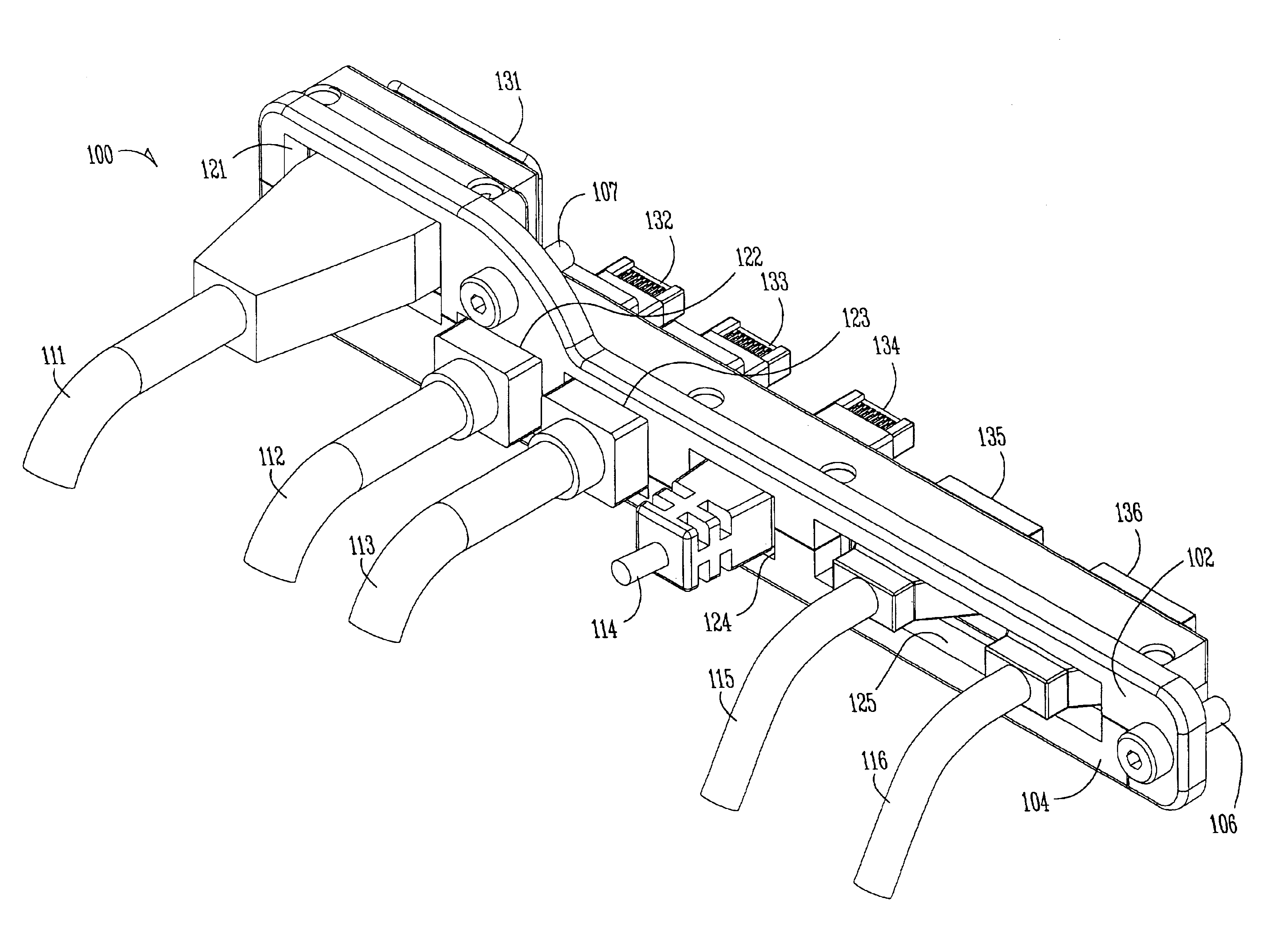
Embodiments of the present invention provide a solution to the need for quick access to electronic modules, such as e-trays, to enable such modules to be inspected, repaired, replaced, or upgraded quickly. Various emb...


PUM


Abstract

An improved rack-mounted server comprises, in one embodiment, a slidable electronics tray having a top cover secured to the rack, to facilitate access to the tray when it is withdrawn from the rack. The tray also includes a camming mechanism to facilitate insertion of the tray into and its extraction from cable connectors or plugs affixed to the rack. The tray includes, in one embodiment, a movement detection mechanism to power it up or down when tray insertion or removal, respectively, is initiated. In addition, the rack includes an improved cable management system that can accommodate different cables and cable plugs. As a tray is inserted into or removed from the rack, corresponding connectors on the tray are electrically coupled to or uncoupled from cable plugs affixed to the rack, eliminating any need to remove cables from the tray or reinstall them.

Description

TECHNICAL FIELDEmbodiments of the present invention relate generally to electronics packaging. More particularly, embodiments of present invention relate to an improved rack-mounted server that facilitates access to and / or replacement of electronics trays, and to methods of use thereof.BACKGROUND INFORMATIONComputer networks, such as the Internet, utilize high performance computer systems called “servers”. Servers typically have high performance processors and contain hardware and software capable of handling large amounts of data. Servers provide a large number of computer users with access to large stores of information. For example, servers are used to host web sites that can be accessed by many computers via the Internet.One or more server components are often housed within a server housing or “server rack”. Server racks are typically box-like structures or cabinets that contain a number of removable electronic modules or electronic trays (“e-trays”). Each e-tray can be a differ...

Claims


Application Information

Patent Timeline
Patent Type & Authority Patents(United States)
IPC IPC(8): H05K7/14
CPCH05K7/1489
Inventor BERRY, WILLIAM E.FITE, ROBERT J.ALDRIDGE, TOMM V.FANEUF, BARRETT M.
Owner INTEL CORP
Why Eureka
Try Eureka