Disk drive

a technology of disk drives and slots, applied in the field of disk drives, can solve the problems of difficulty in further reducing the size and thickness of conventional slot-in-type disk drives, and achieve the effect of reducing size and thickness

Inactive Publication Date: 2005-01-04
PANASONIC CORP
View PDF10 Cites 37 Cited by
  • Summary
  • Abstract
  • Description
  • Claims
  • Application Information

AI Technical Summary

Benefits of technology

In order to overcome the problems described above, an object of the present invention is to provide a slot-in type disk drive of a reduced size and thickness.

Problems solved by technology

Thus, it is difficult to further reduce the size and thickness of the conventional slot-in type disk drive.

Method used


Image

  • Disk drive
  • Disk drive
  • Disk drive

Examples


embodiment 1

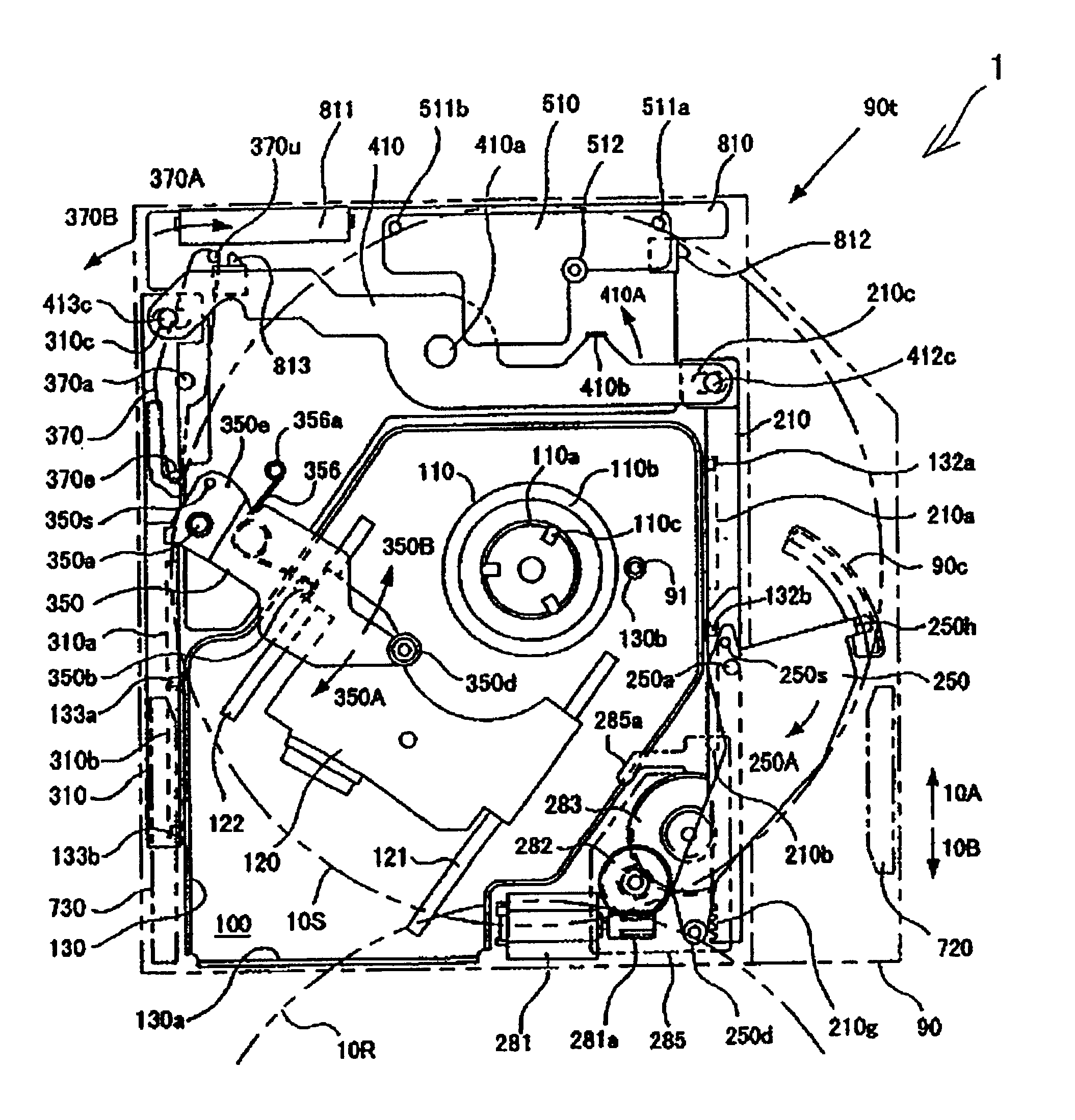
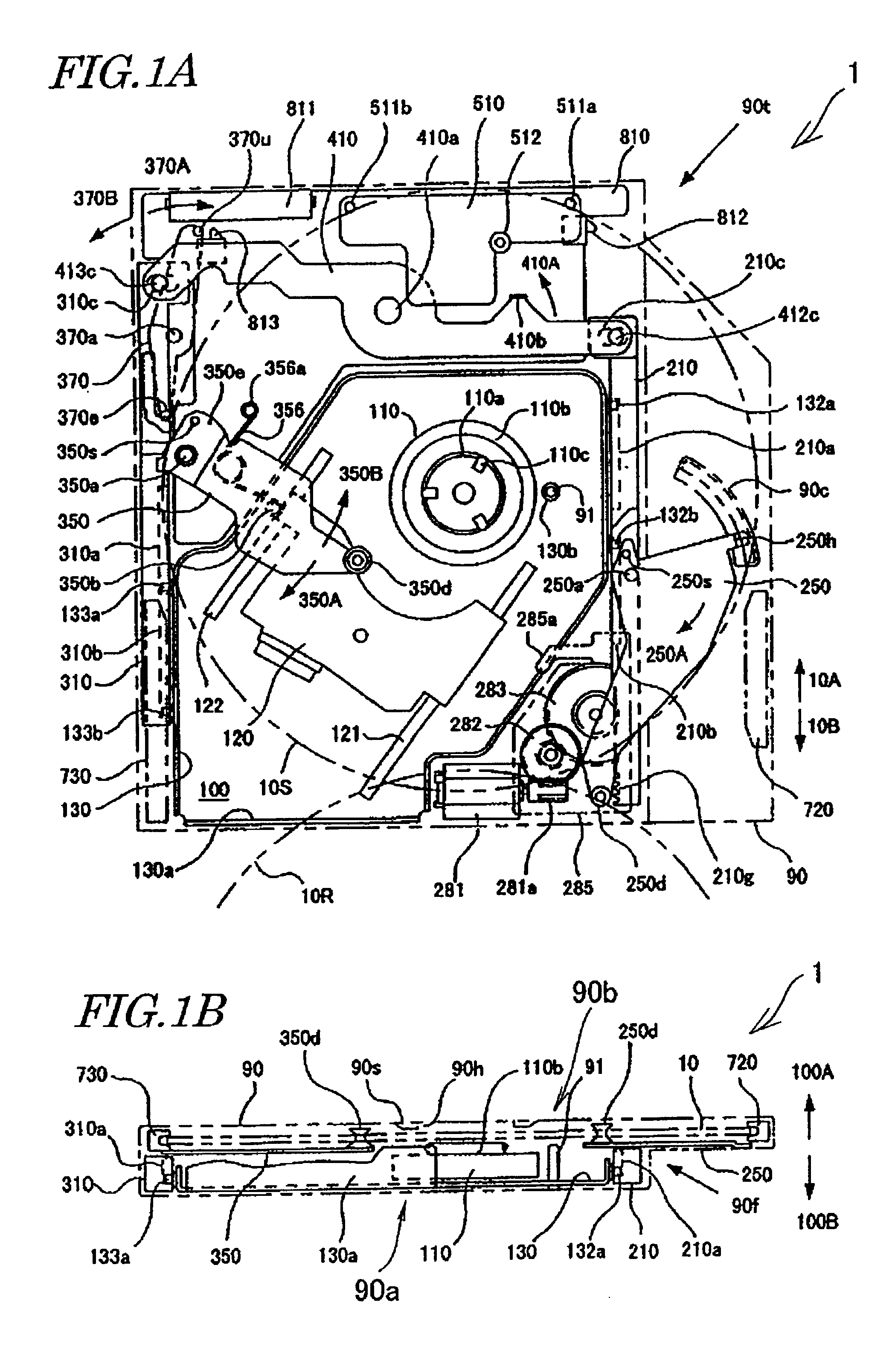
Hereinafter, a disk drive according to a first specific preferred embodiment of the present invention will be described with reference to the accompanying drawings. First, an overall arrangement for the disk drive will be described with reference to FIGS. 1A and 1B. FIG. 1A is a plan view of the disk drive 1 of the first preferred embodiment as viewed vertically to the direction in which a disk 10 is transported. FIG. 1B is a front view of the disk drive 1 shown in FIG. 1A as viewed in the direction 10A. That is to say, the disk drive 1 shown in FIG. 1B is viewed in the disk loading direction. It should be noted that a direction indicated by an arrow will be herein simply referred to as a “direction” and identified by the reference numeral attached to the arrow, e.g., the direction indicated by the arrow 10A will be herein simply referred to as “the direction 10A”.

The disk drive 1 of this preferred embodiment includes outer casing 90, base 100, first and second rockers 250 and 350 a...

embodiment 2

Hereinafter, a disk drive according to a second specific preferred embodiment of the present invention will be described. First, an overall arrangement for the disk drive 2 will be described with reference to FIGS. 8A, 8B and 8C. FIG. 8A is a plan view of the disk drive 2 of the second preferred embodiment as viewed vertically to the direction in which the disk 10 is transported. FIG. 8B is a front view of the disk drive 2 shown in FIG. 8A as viewed in the direction 10A. FIG. 8C is a partially cross-sectional, front view illustrating the inside of the disk drive 2 shown in FIG. 8A as viewed in the direction 10A.

In FIGS. 8A, 8B and 8C, each member having substantially the same function as the counterpart of the first preferred embodiment is identified by the same reference numeral. Thus, the following description will mainly relate to the differences between the first and second preferred embodiments.

Like the disk drive 1 of the first preferred embodiment, the disk drive 2 of the sec...


PUM

PropertyMeasurementUnit
timeaaaaaaaaaa
diameteraaaaaaaaaa
diameteraaaaaaaaaa

Abstract

A disk drive includes base with a spindle motor, first and second rockers and first and second sliders. The spindle motor has a turntable to mount a disk. The first and second rockers rock substantially parallelly to the turntable. The first rocker pulls in the disk, inserted externally, to a position where the disk and motor have their centers aligned. The second rocker unloads the disk from the position to a point where the disk is exposed partially. The first and second sliders are engaged with the first and second rockers to make them pull in and unload the disk, respectively, and reciprocate substantially parallelly to the turntable. The rockers and sliders are located under the turntable. The slider(s) support(s), raise(s) and lower(s) a side face of the base through the reciprocation.

Description

BACKGROUND OF THE INVENTION1. Field of the InventionThe present invention relates to a disk drive for reading and / or writing information from / on a disk storage medium such as a CD or a DVD. More particularly, the present invention relates to a disk drive of a so-called “slot-in” type into / from which the user can externally load and automatically unload a disk directly.2. Description of the Related ArtA conventional disk drive includes a tray for use to load and unload a disk into / from the disk drive. In operating a disk drive of this type, the user gets the tray drawn out, mounts a disk on the tray, and then gets the tray inserted along with the disk, thereby loading the disk into the disk drive.Another conventional disk drive requires the user to open and close a disk loading / unloading lid or cover to mount and dismount a disk directly on / from a turntable.On the other hand, a disk drive of a different type, having a mechanism that does not require the user to get the tray drawn out...

Claims


Application Information

Patent Timeline
Patent Type & Authority Patents(United States)
IPC IPC(8): G11B17/04
CPCG11B17/0404
Inventor SAJI, YOSHITOINATA, MASAHIROWADA, SHINICHIOHTA, HIDEHIKOMASAOKA, KENGO
Owner PANASONIC CORP
Why Eureka
Try Eureka