Actuating mechanism for a turbine and method of retrofitting

a technology of actuating mechanism and turbine, which is applied in the direction of engine seals, machines/engines, leakage prevention, etc., can solve the problems of gas or steam leakage, affecting and generally undesirable, and reducing the efficiency of gas turbines

Inactive Publication Date: 2005-01-11
GENERAL ELECTRIC CO
View PDF15 Cites 85 Cited by
  • Summary
  • Abstract
  • Description
  • Claims
  • Application Information

AI Technical Summary

Problems solved by technology

Gas or steam leakage, either out of the gas or steam path or into the gas or steam path, from an area of higher pressure to an area of lower pressure, is generally undesirable.
For example, a gas path leakage in the turbine or compressor area of a gas turbine, between the rotor of the turbine or compressor and the circumferentially surrounding turbine or compressor casing, will lower the efficiency of the gas turbine leading to increased fuel costs.
Also, steam-path leakage in the turbine area of a steam turbine, between the rotor of the turbine and the circumferentially surrounding casing, will lower the efficiency of the steam turbine leading to increased fuel costs.
While labyrinth seal carriers, singly or in combination with brush seals, have proved to be quite reliable, performance of labyrinth seal carriers degrades over time as a result of transient events in which the stationary and rotating components interfere, rubbing the labyrinth teeth into a “mushroom” profile and opening the seal clearance.

Method used


Image

  • Actuating mechanism for a turbine and method of retrofitting
  • Actuating mechanism for a turbine and method of retrofitting
  • Actuating mechanism for a turbine and method of retrofitting

Examples


Embodiment Construction

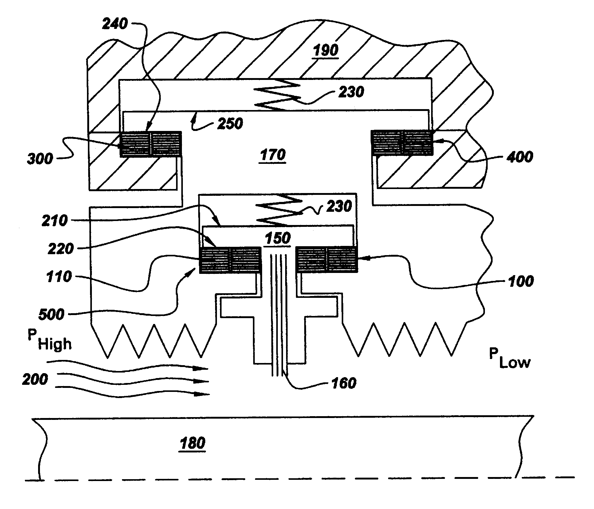
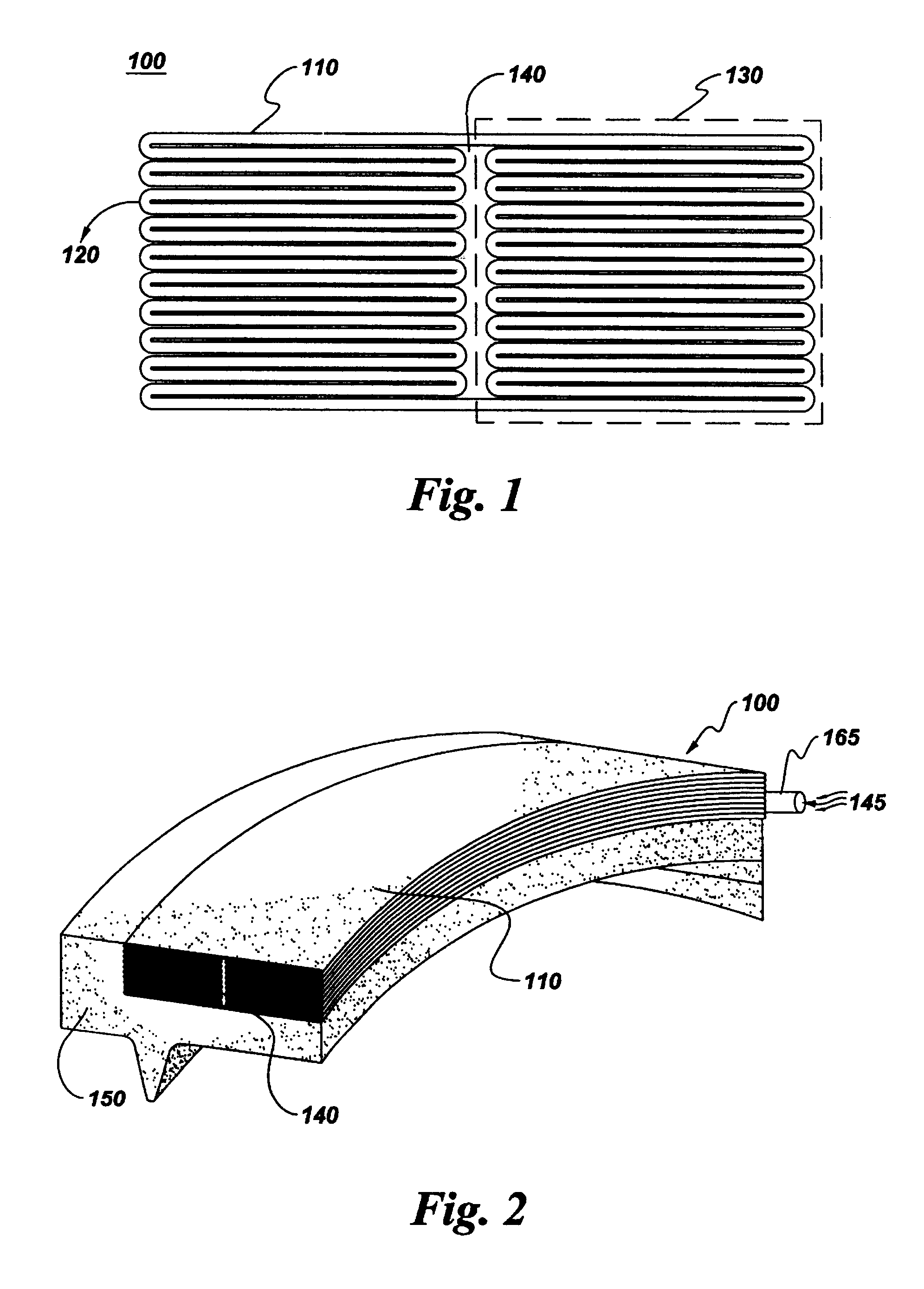
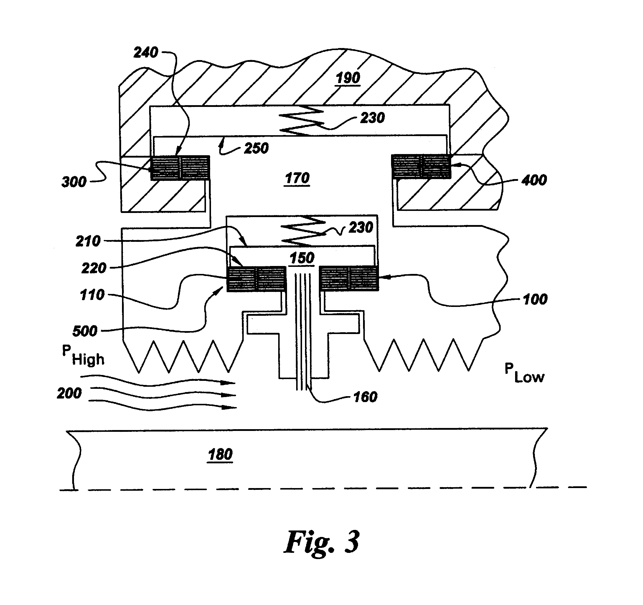
An actuating mechanism, generally designated 100, typically comprises at least one compliant member 110 having a series of serpentine folds 120 forming a plurality of fold sections 130 (see FIG. 1). At least one central cavity 140 is interposed between the adjacent fold sections 130 wherein the compliant member 110 is movable between a first retracted position and a second extended position upon introduction of a pressurized medium 145 (FIG. 2), such as, for example, gas or steam, into the central cavity 140 and dispersion of the pressurized medium 145 within the serpentine folds. FIG. 6, shows actuating mechanism 100 displaced in the second extended position (a radially outward position).

FIG. 2 shows actuating mechanism 100 disposed on a seal carrier 150. As used herein, “on”, “over”, “above”, “under” and the like are used to refer to the relative location of elements of actuating mechanism 100 as illustrated in the Figures and is not meant to be a limitation in any manner with res...


PUM


Abstract

One embodiment of the present invention comprises an actuating mechanism for a turbine comprising a compliant member (meaning at least one compliant member) comprising a series of serpentine folds forming a plurality of fold sections and a central cavity (meaning at least one central cavity) interposed between the adjacent fold sections wherein the compliant member is movable between a first retracted position and a second extended position upon introduction of a pressurized medium into the central cavity and dispersion of the pressurized medium within the serpentine folds.

Description

BACKGROUND OF THE INVENTIONThe present invention relates generally to rotary machines, and more particularly to actuated seals for rotary machines such as steam and gas turbines.Rotary machines include, without limitation, turbines for steam turbines and compressors and turbines for gas turbines. A steam turbine has a steam path that typically includes, in serial-flow relationship, a steam inlet, a turbine, and a steam outlet. A gas turbine has a gas path which typically includes, in serial-flow relationship, an air intake (or inlet), a compressor, a combustor, a turbine, and a gas outlet (or exhaust nozzle). Gas or steam leakage, either out of the gas or steam path or into the gas or steam path, from an area of higher pressure to an area of lower pressure, is generally undesirable. For example, a gas path leakage in the turbine or compressor area of a gas turbine, between the rotor of the turbine or compressor and the circumferentially surrounding turbine or compressor casing, will...

Claims


Application Information

Patent Timeline
Patent Type & Authority Patents(United States)
IPC IPC(8): F16J15/44
CPCF16J15/445F16J15/442
Inventor DINC, OSMAN SAIMDEMIROGLU, MEHMETSARSHAR, HAMID REZAGLADEN, PAULHOCHHALTER, KEITH
Owner GENERAL ELECTRIC CO
Why Eureka
Try Eureka