Fan assembly for an umbrella

Inactive Publication Date: 2005-01-11
GREAT IMPORTANCE
View PDF16 Cites 7 Cited by
  • Summary
  • Abstract
  • Description
  • Claims
  • Application Information

AI Technical Summary

Benefits of technology

It is a further object of this invention to provide such a fan assembly which is easy to assemble.
It is a further object of this invention to provide such a fan assembly which can be manufactured and sold at a low cost.
It is a further object of this invention to provide such a fan assembly which can be easily slid down or decoupled from the umbrella pole when the umbrella canopy is folded down and not in use and then slid back up the umbrella pole and into position or coupled to the pole when the umbrella canopy is deployed.
It is a further object of this invention to provide such a fan assembly which has easily removable contoured fan blades.
It is a further object of this invention to provide such a fan assembly which does not require multiple drive pinions or a special gear key.
The invention results from the realization that a self contained, universal, and low cost, umbrella fan assembly which is easy to assemble and disassemble is preferably effected by three separate assemblies: a split collar clampable around the umbrella pole, a motor housing supported by the split collar, and a separate fan blade drive ring with an integral gear also supported by the split collar. This preferred design is in sharp contrast with the assembly of U.S. Pat. No. 5,007,811 in which the drive ring is an integral part of the motor housing and thus requires expensive bearings and a complex drive train to accommodate the slot in the motor housing.

Problems solved by technology

The design constraints associated with such an umbrella fan include the fact that the umbrella canopy is often lowered when not in use by the action of a slide which surrounds the umbrella pole operated by a crank mechanism which also surround the umbrella pole.
Accordingly, this assembly is not designed as an after-market fan which can be used in conjunction with a wide variety of umbrellas previously purchased by consumers.
Since, in the design of the '811 patent, the drive ring is an integral part of the fan motor housing, the resulting structure is necessarily complex and difficult to manufacture at a low cost.
Finally, the '188 patent notes that the fan assembly of the '811 patent is unstable.

Method used


Image

  • Fan assembly for an umbrella
  • Fan assembly for an umbrella
  • Fan assembly for an umbrella

Examples


Embodiment Construction

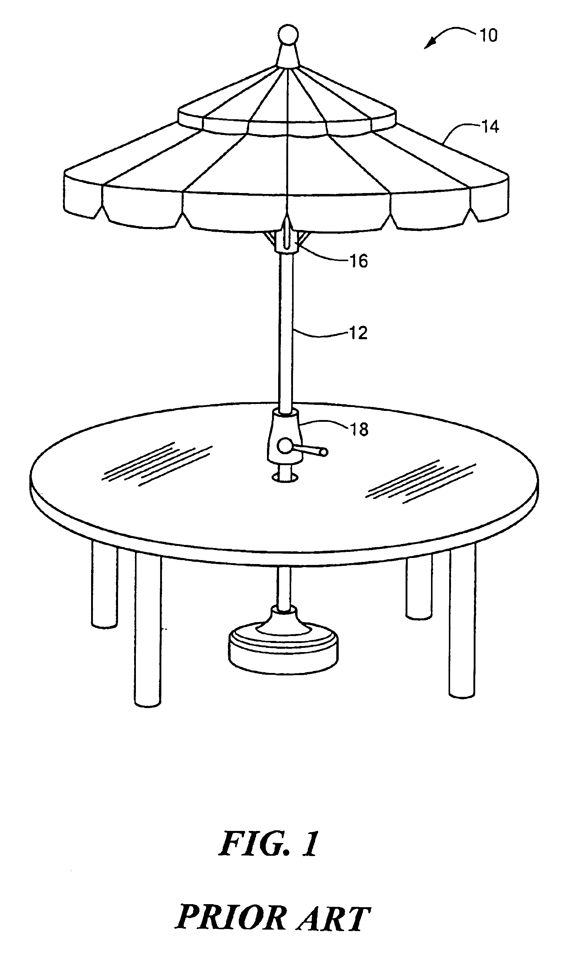
Conventional umbrella 10, FIG. 1 includes pole 12 and canopy 14 which is lowered and raised as slide 16 moves up and down on pole 12 by the operation of crank mechanism 18.

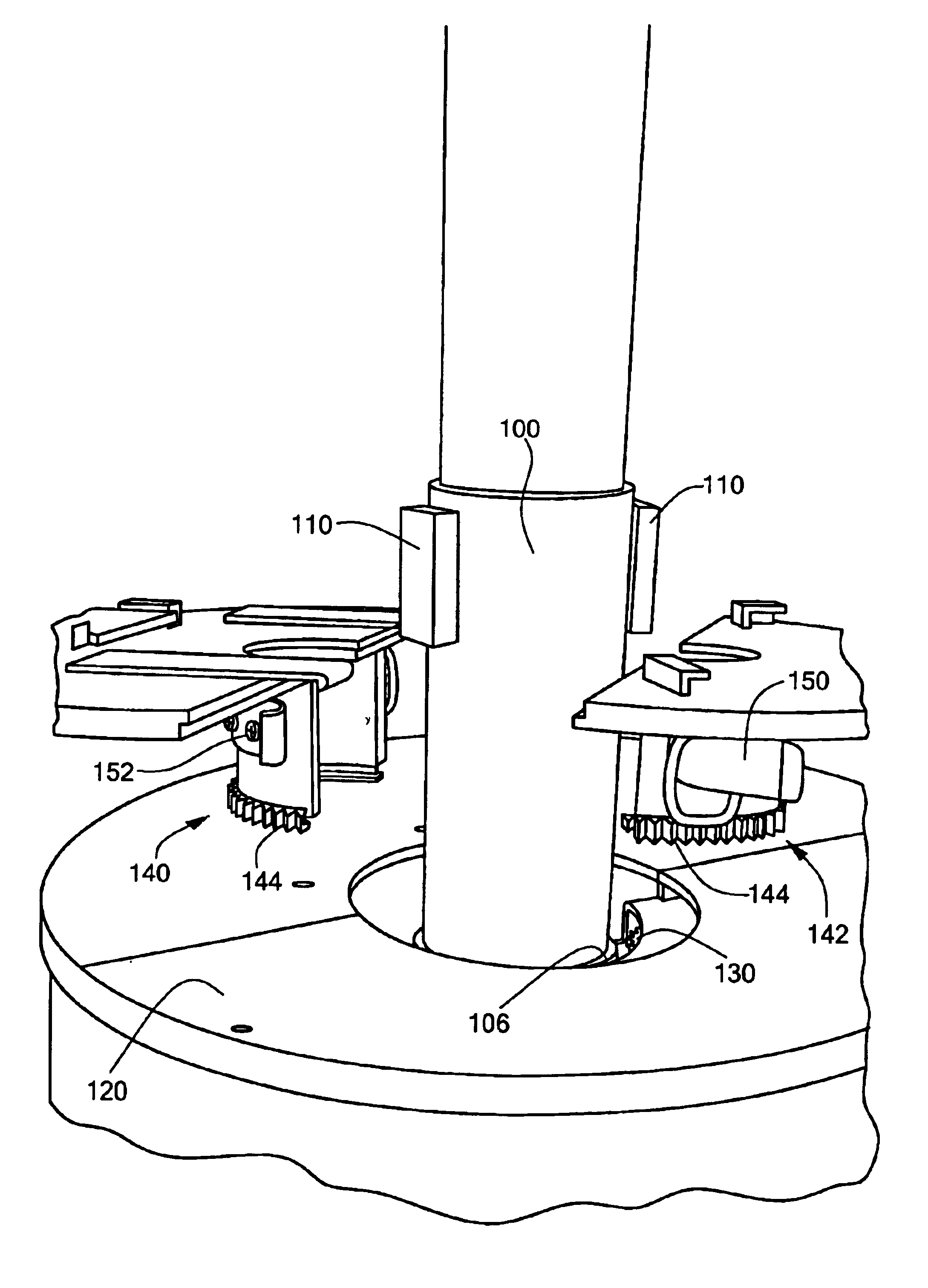
Thus, many consumers have existing umbrellas which cannot accommodate a fan assembly unless it can be easily coupled about pole 12 between clamp mechanism 18 and slide 16. In addition, when umbrella 10 is not in use and canopy 14 is folded downward, the fan assembly must be moveable down the pole or easily decoupled from the pole so it does not interfere with the operation of slide 16. In addition, any after-market fan assembly design must take into account the fact that the umbrella is often lowered when not in use. Thus, the fan assembly must be easily coupled by the consumer to the pole between the crank mechanism and the slide but also quickly movable down or decoupled from the pole. In addition, any marketable fan assembly must be self-contained, low cost, universal in design, safe, and preferably battery ope...


PUM


Abstract

A fan assembly with a split collar clampable about a pole, the split collar including a drive ring support. A split motor housing is clampable about the split collar and the split motor housing includes a drive mechanism. A split drive ring is rotatably clampable about the split collar and supported by the drive ring support. The split drive ring includes a driven mechanism driven by the drive mechanism. A plurality of fan blades are coupled to the split drive ring.

Description

FIELD OF THE INVENTIONThis invention relates to a fan assembly for an umbrella and also to a fan assembly which can be coupled to a pole even without an umbrella.BACKGROUND OF THE INVENTIONThere has long been a need for a self-contained, easy to assemble, low cost, universal, and safe umbrella fan. The design constraints associated with such an umbrella fan include the fact that the umbrella canopy is often lowered when not in use by the action of a slide which surrounds the umbrella pole operated by a crank mechanism which also surround the umbrella pole. Thus, any useful after-market umbrella fan assembly must be able to be easily coupled by the consumer to the umbrella pole between the crank mechanism and the umbrella canopy slide.U.S. Pat. No. 6,017,188 discloses a fan assembly permanently disposed on the umbrella pole above the slide. Accordingly, this assembly is not designed as an after-market fan which can be used in conjunction with a wide variety of umbrellas previously pu...

Claims


Application Information

Patent Timeline
IPC IPC(8): F04D25/08A45B3/00F04D25/02
CPCA45B3/00F04D25/088A45B2200/1036A45B2023/0012
Inventor COHEN, RONALD B.WALLEN, WAYNE
Owner GREAT IMPORTANCE
Why Eureka
Try Eureka