Medical clip applier safety arrangement

a clip and safety arrangement technology, applied in the field of medical clip devices, can solve the problems of unintentional manipulation, slippage of clip or clip from the jaw, etc., and achieve the effect of facilitating the keeping of the jaws

Inactive Publication Date: 2005-01-11
MICROLINE SURGICAL INC
View PDF1 Cites 204 Cited by
  • Summary
  • Abstract
  • Description
  • Claims
  • Application Information

AI Technical Summary

Benefits of technology

The jaws are movably supported between an upper housing half, called a “cinch”, and a stationary lower housing half called a “brace. The jaws each have an upstanding “limiting” pin on each leg thereof. Each pin is arranged to slide within a respective track disposed on an inner surface wall of the cinch, and each pin may be lodged into a pocket at the distal end of each track to limit or prevent inadvertent closure of the jaws at that point. The jaw pins, when slid into the pockets in the cinch thus prevent the jaws from accidentally closing or pinching a clip or staple between those jaws and force the jaws open before the clip goes between the jaws. The wings on the elongated cross-shaped push member fit into the same track in the jaws as do the generally U-shaped clips do as they are being pushed distally or forwardly and prevent the jaws from partially closing to otherwise partially squeeze a staple or clip and thus have the clip fall accidently into a patient. The outer edges of the wings slide between the jaws as they biasedly spread apart or open so as to enable it to receive the fully spread open generally U-shaped clip as it is being pushed therebetween. This opening of the jaws and distal motion by the outermost ends of the wings of the cross-shaped member occurs as the jaws are being permitted to reopen to accept a new, open U-shaped clip member, ready for a further clip actuation on body tissue. Those wings on the cross-shaped member and the pins on the jaws engaged in the pockets of the cinch work simultaneously to provide the locking open of the jaws for proper receipt of the U-shaped clip therebetween and for proper opposed alignment of the jaws.
The distalmost finger of the elongated spring is in rubbing, biased engagement with the underside of the generally cross-shaped pusher member. The biased spring thus also keeps the elongated cross-shaped pusher member in contact with the shoulders or ledges on the inner edges of each respective jaw and keeps the pusher member behind the clip during loading thereof so as to prevent slipping and misfiring of that clip. By maintaining a biased pressure against the jaws in that manner, the jaws are prevented from crossing or misaligning with one another when those jaws are being squeezed together and closing in on a U-shaped clip therebetween. The jaws are thus accurately “opposed” with respect to one another, because of their receipt of a biased pusher and alignment cross arranged therebetween.
Each of the jaws may have an inner edge with a shoulder extending therealong, for guided receipt of a clip and for stabilizing receipt of the cross-shaped pusher member. The cross-shaped member includes a pair of wing members extending therefrom, each of the wing members mating with the shoulder to keep the jaws spread apart after a clip has been fed therebetween. The cross-shaped member includes a pair of wings laterally disposed thereon, so as to slidably engage the shoulders in the jaws to keep the jaws open when the cross-shaped member is pushed distally, behind the clip when it is loaded, and to thus prevent the jaws from being inadvertently closed on a staple or clip therebetween.
Each of the wings may have an outer edge thereon for respective engagement with each of the jaws during opening of the jaws during distal motion of the cross-shaped member with respect to the lower housing. Each of the jaws has an upstanding pin thereon for sliding engagement into a pocket in the cinch to prevent accidental closing of the jaws.
The method may include arranging an outer edge of each wing on the distal end of the pusher member into engagement with the jaws to facilitate the keeping open of the jaws after distal movement of the clip pusher member between the jaws, and after pushing a clip into position between the jaws by engagement of a pair of upstanding rails in the pusher member with a bridging portion of the clip.

Problems solved by technology

A problem arises occasionally wherein the staple or clip may slip from those jaws as those jaws are unintentionally manipulated and the staple gets lost at the body treatment site.

Method used


Image

  • Medical clip applier safety arrangement
  • Medical clip applier safety arrangement
  • Medical clip applier safety arrangement

Examples


Embodiment Construction

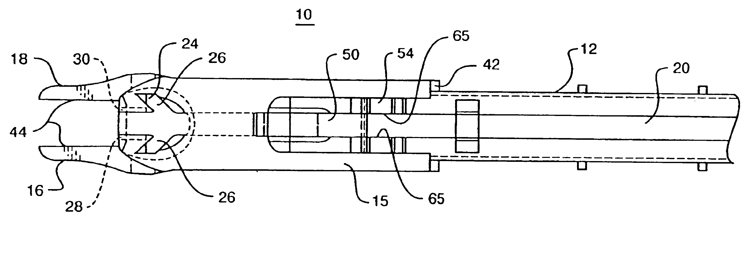
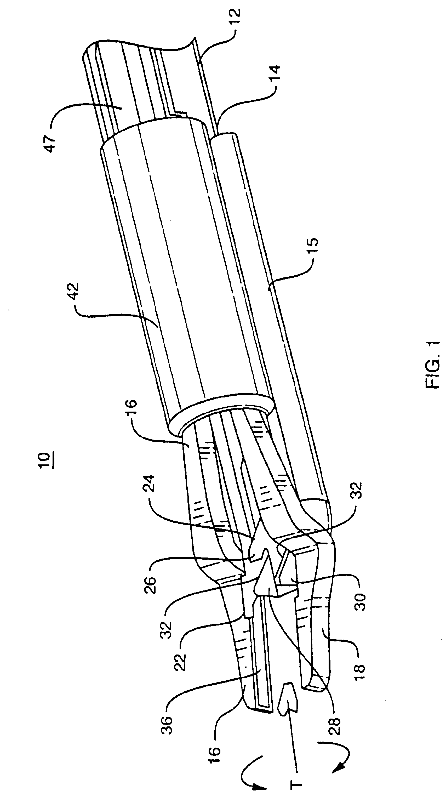
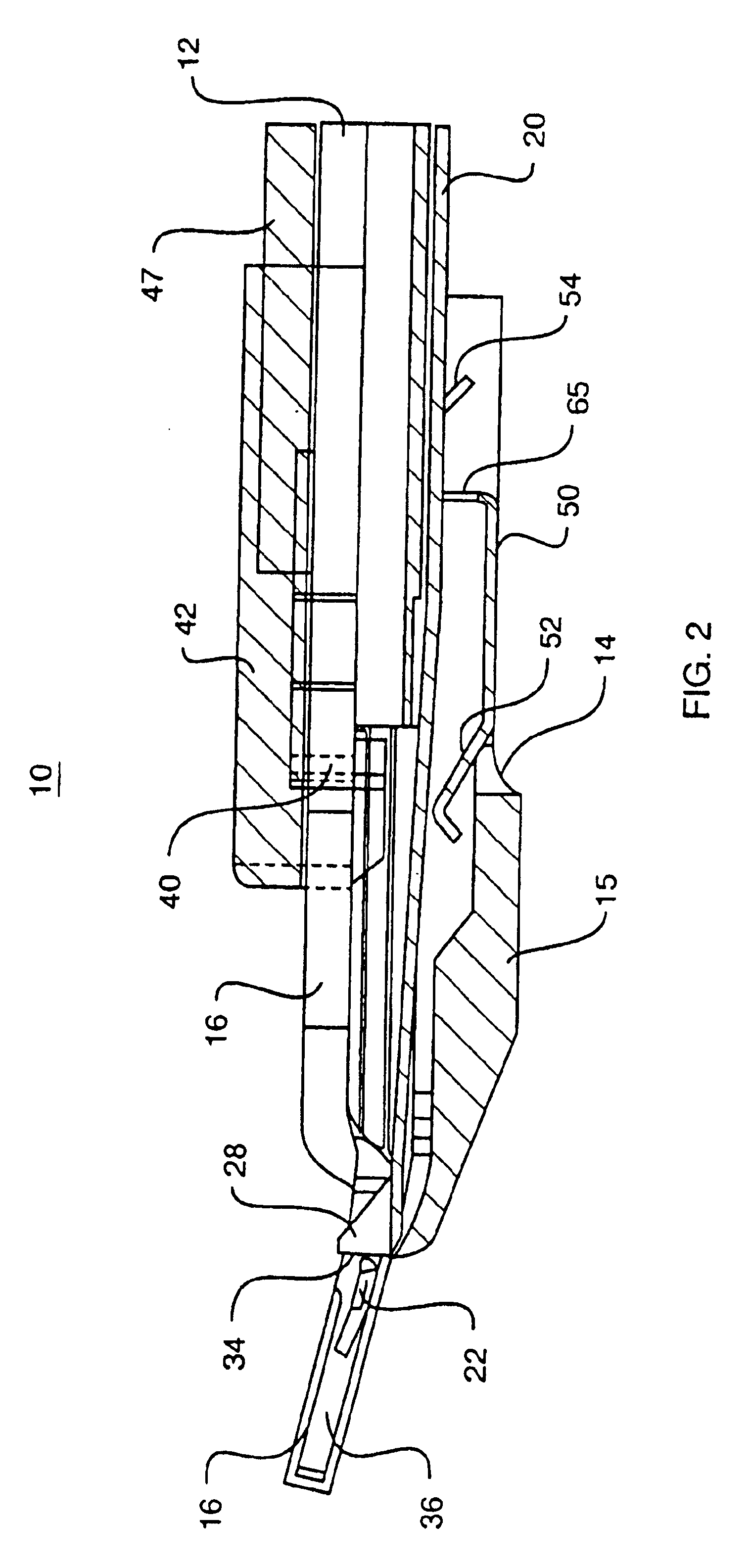
Referring now to the drawings and particularly to FIG. 1, there is shown the present invention which comprises a medical clip applying device 10 comprises an elongated beam 12 having a proximal end (not shown here for clarity) and a distal end 14 fixedly secured to a stationary lower housing or brace 15. A pistol-like handle (not shown) is arranged at the proximal end, with a trigger mechanism arranged with an elongated coupling connected to a pair of jaws 16 and 18 so as to permit the jaws 16 and 18 to be squeezed together as the attending physician pulls on the trigger.

A pusher mechanism is arranged with the handle (not shown for clarity), the pusher 20, as may be seen in FIGS. 2, 3b, 3c, 4 and 7, has a distalmost end, which sequentially pushes staples or clips 22, as shown in phantom in FIG. 1, into a position between the jaws 16 and 18 before the jaws 16 and 18 are squeezed together at the distalmost end of the medical clip device 10. The distalmost end of the pusher 20 in this ...


PUM


Abstract

A medical clip dispenser apparatus for the pinching of a medical clip or staple about a portion of a mammalian body tissue. The apparatus comprises an elongated support beam having a distal end with a stationary lower housing thereon, and a distally movable hollow cinch slidably disposed on the lower housing. The cinch has a portion of a pair of closable jaws squeezably arranged therewithin. An elongated pusher has a generally cross-shaped pusher member on a distal end thereof in slidable engagement with the jaws, to keep the jaws apart from one another after a new clip has been pushed into position between the jaws.

Description

BACKGROUND OF THE INVENTION1. Field of the InventionThis invention relates to medical clip devices and more particularly to guidance and alignment arrangements on the tip of those medical clip devices, and is co-pending with and a continuation in part of commonly assigned U.S. patent applications Ser. Nos. 09 / 795,808, entitled “Release Mechanism for a Grasping Device” filed Feb. 28, 2001 and Serial No. 09 / 934,378, entitled “Safety Locking Mechanism for a Medical Clip Device” and filed Aug. 21, 2001, as all of which are incorporated herein by reference in their entirety.2. Prior ArtMedical clip devices are utilized to pinch and shut off a body tissue. The clip device usually comprises an elongated support arm having a distal end comprising a pair of squeezable jaws. Medical clip devices are shown in U.S. Pat. Nos. 6,277,131 to Kalikow, and Ser. No. 6,306,141 to Meade, each of which are also incorporated herein by reference. Typically a staple or squeezable wire is pushed tightly betw...

Claims


Application Information

Patent Timeline
Patent Type & Authority Patents(United States)
IPC IPC(8): A61B17/12A61B17/128
CPCA61B17/1285
Inventor MANETAKIS, EMMANUELDE GUILLEBON, HENRI
Owner MICROLINE SURGICAL INC
Why Eureka
Try Eureka