Display with aligned optical shutter and backlight cells applicable for use with a touchscreen

a touchscreen and backlight technology, applied in the field of displays, can solve the problem of reducing the brightness of the display in all viewing conditions

Inactive Publication Date: 2005-01-11
GOOGLE TECH HLDG LLC
View PDF26 Cites 147 Cited by
  • Summary
  • Abstract
  • Description
  • Claims
  • Application Information

AI Technical Summary

Problems solved by technology

The filter, however, reduces the brightnes

Method used


Image

  • Display with aligned optical shutter and backlight cells applicable for use with a touchscreen
  • Display with aligned optical shutter and backlight cells applicable for use with a touchscreen
  • Display with aligned optical shutter and backlight cells applicable for use with a touchscreen

Examples


Embodiment Construction

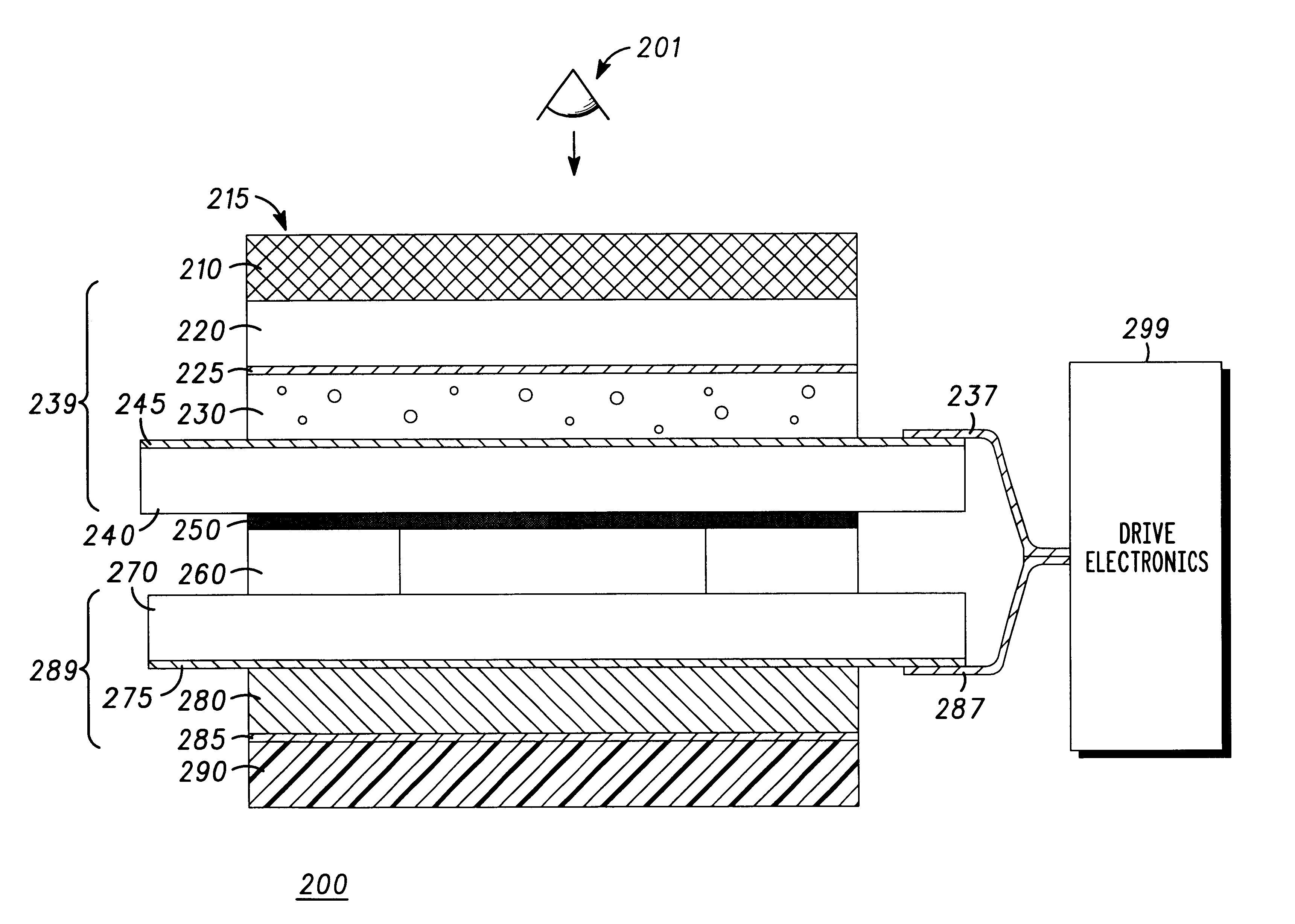
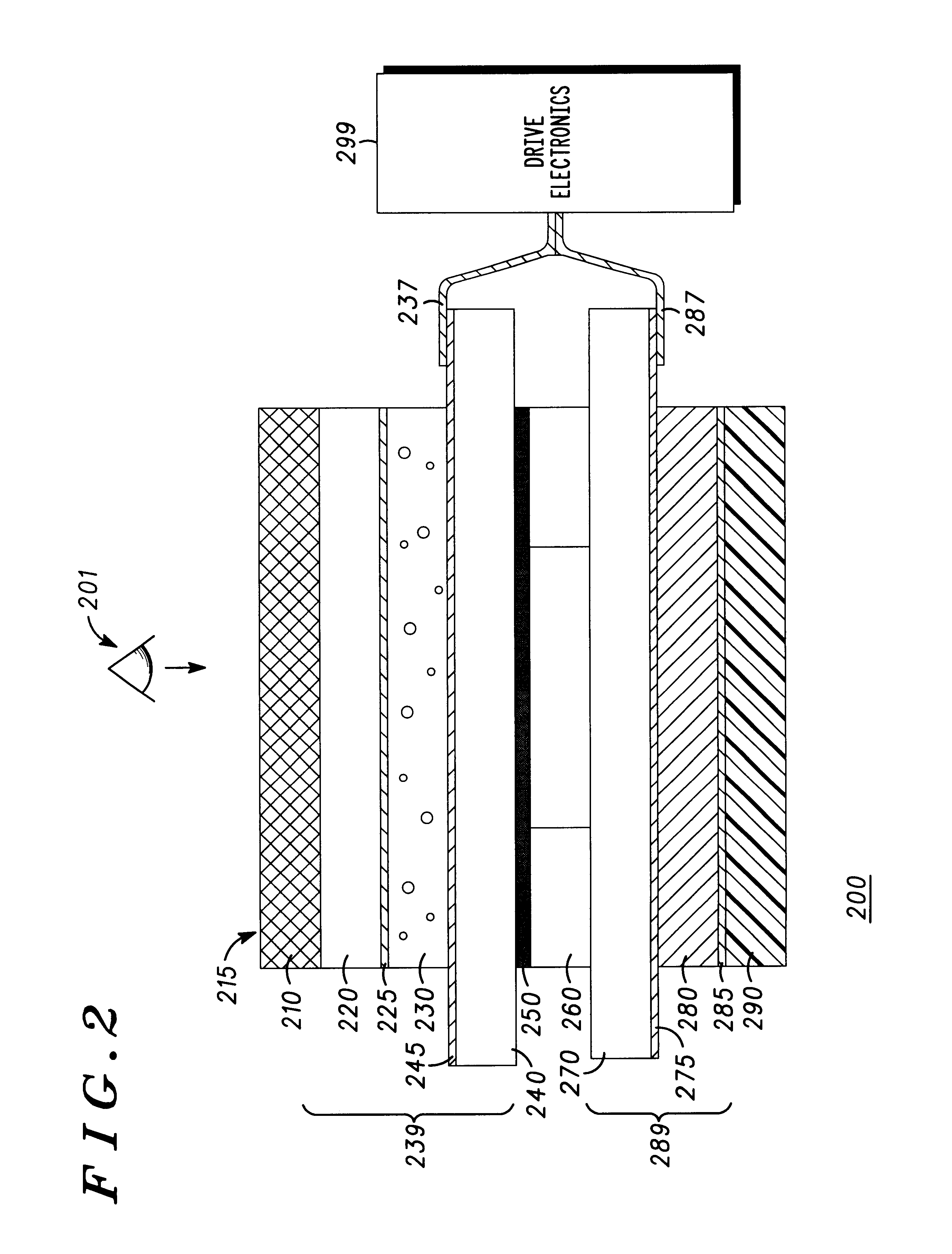
A display with aligned optical shutter and backlight cells uses a patterned polymer-dispersed liquid crystal (PDLC) optical shutter and a patterned electroluminescent (EL) backlight to provide a low-cost, low-current-drain display having good contrast in both bright-light and low-light conditions. The aligned, patterned optical shutter and backlight layers form pixel “windows” through which images printed on a background can be hidden or revealed. Specifically, a black mask bears the images and is inserted between the optical shutter and the backlight layers to show information images, cover inactive areas of the display, and cover electrode traces connecting active segments of the display.

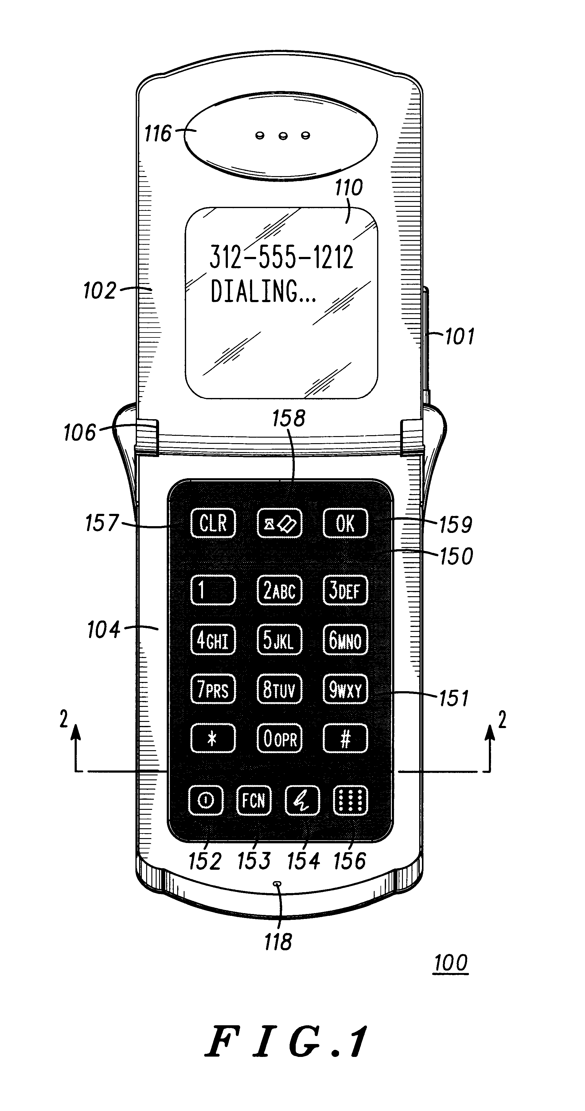
The display with aligned optical shutter and backlight cells is thin and flexible enough to be integrated with a touchscreen. The display can be used to implement a keypad for a portable electronic device, such as a radiotelephone, by exhibiting the numbers and icons common to such user interfaces...


PUM

PropertyMeasurementUnit
Flexibilityaaaaaaaaaa
Shapeaaaaaaaaaa
Electroluminescenceaaaaaaaaaa

Abstract

A display (200) with aligned optical shutter and backlight cells (239, 289) uses a patterned polymer-dispersed liquid crystal (PDLC) optical shutter material (230) and an electroluminescent (EL) backlight material (280) to provide a low-cost, low-current-drain display having good contrast in both bright-light and low-light conditions. The aligned, patterned optical shutter and backlight layers form pixel “windows” through which images printed on a background can be hidden or revealed. Specifically, a mask layer (250) bears the images and is inserted between the optical shutter and the backlight layers to show information images, cover inactive areas of the display, and cover electrode traces connecting active segments of the display. The display (200) is thin and flexible enough to be integrated with a touchscreen (290).

Description

FIELD OF THE INVENTIONThis invention relates generally to displays, and more particularly to an optical shutter-type display having a light source and applicable for use with a touchscreen.BACKGROUND OF THE INVENTIONCertain portable electronic devices, such as radiotelephones, must be visible in both low-light and bright-light environments. A standard emissive display uses a pixelated, or patterned, light source in which different regions of the display can be selectively turned on to emit light. Regions of the display that are turned off do not emit light; however, in bright light situations, the “off” portion of the display can be as bright or brighter than the “on” portion of the display due to the highly reflective nature of the light-emitting materials (generally phosphors). A contrast filter, also called a neutral density filter, can be placed over the display and uses a partially light-absorbing film to absorb some of the emitted and reflected light from the display. The filt...

Claims


Application Information

Patent Timeline
IPC IPC(8): G02F1/1335G02F1/13G09G3/34H04M1/22G02F1/133G02F1/1334G02F1/1333G02F1/13357G09F9/00G09G3/20G09G3/36
CPCG02F1/133603G06F3/0412G06F3/03547G09G3/342H04M1/22G02F1/13338G02F1/1334G02F1/133621B05D5/06E05B1/04
Inventor AKINS, ROBERT B.PAITL, KENVENTOURIS, GEORGE M.CHARLIER, MICHAEL L.
Owner GOOGLE TECH HLDG LLC
Why Eureka
Try Eureka