
Electrical connector having terminals with reinforced interference portions

a technology of interference blocks and terminals, which is applied in the direction of fixed connections, coupling device connections, electrical apparatus construction details, etc., can solve the problems of disruption or failure of the electrical connection between the lga chip and the pcb, and the terminal b>6/b> not being securely fastened in the passageway

Inactive Publication Date: 2005-01-18
HON HAI PRECISION IND CO LTD
View PDF5 Cites 82 Cited by
  • Summary
  • Abstract
  • Description
  • Claims
  • Application Information

AI Technical Summary

Benefits of technology

In order to achieve the above object, an electrical connector in accordance with the present invention comprises an insulative housing and a plurality of terminals. The housing defines a plurality of passageways receiving the terminals therein. Each passageway comprises a narrow first passage and a broad second passage in communication with one end of the first passage. The first passage has two stepped interior sidewalls each with a first sidewall and a second sidewall. A space between the opposite first sidewalls is greater than that between the opposite second sidewalls. Each terminal comprises a pair of retention portions. Each retention portion itself is separated thereby forming a first interference portion and a second interference portion. The first interference portion is wider than the second interference portion in an axis parallel to a top face of the retention portion. The first interference portion of the retention portion interferentially engages with the first sidewall of the passageway. The second interference portion of the protrusions interferentially engages with the second sidewall of the passageway. Thus, the terminal can be securely received in the passageway of the housing.

Problems solved by technology

When this happens, interferential force between the terminal 6 and the housing in the passageway is reduced, resulting in the terminal 6 not being securely fastened in the passageway.
This can lead to disruption or failure of electrical connection between the LGA chip and PCB.

Method used


Image

  • Electrical connector having terminals with reinforced interference portions
  • Electrical connector having terminals with reinforced interference portions
  • Electrical connector having terminals with reinforced interference portions

Examples


Embodiment Construction

Reference will now be made to the drawings to describe the present invention in detail.

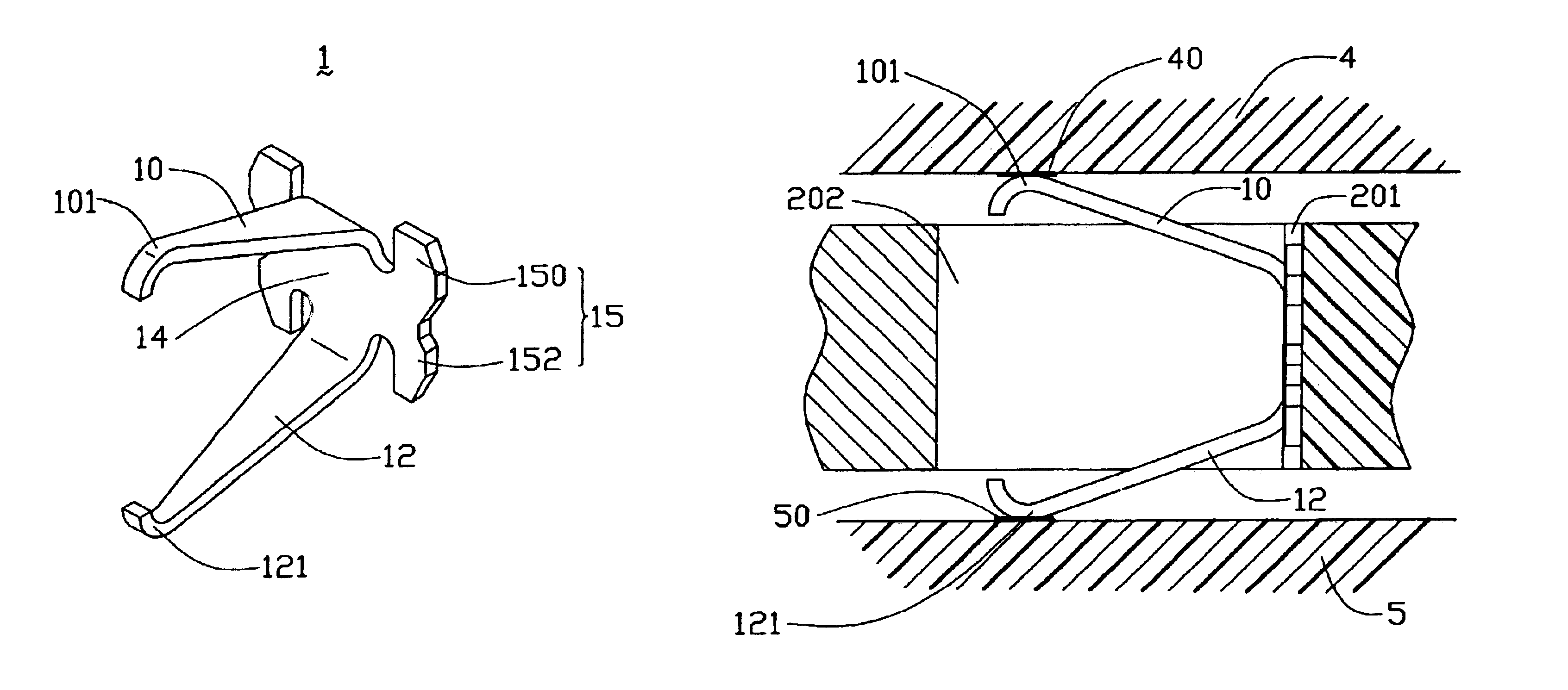
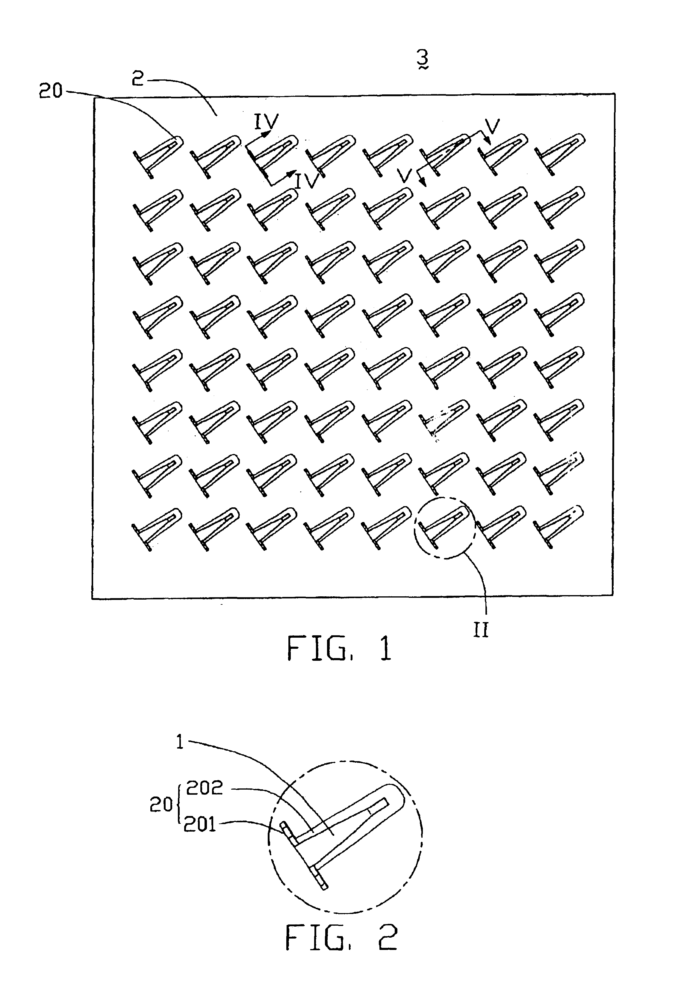
Referring to FIGS. 1 and 6, an LGA electrical connector 3 in accordance with the preferred embodiment of the present invention is adapted for electrically connecting an LGA chip 4 with a PCB 5. The LGA connector 3 comprises an insulative housing 2, and a multiplicity of terminals 1 arranged in a multiplicity of passageways 20 of the housing 2 in a rectangular array.

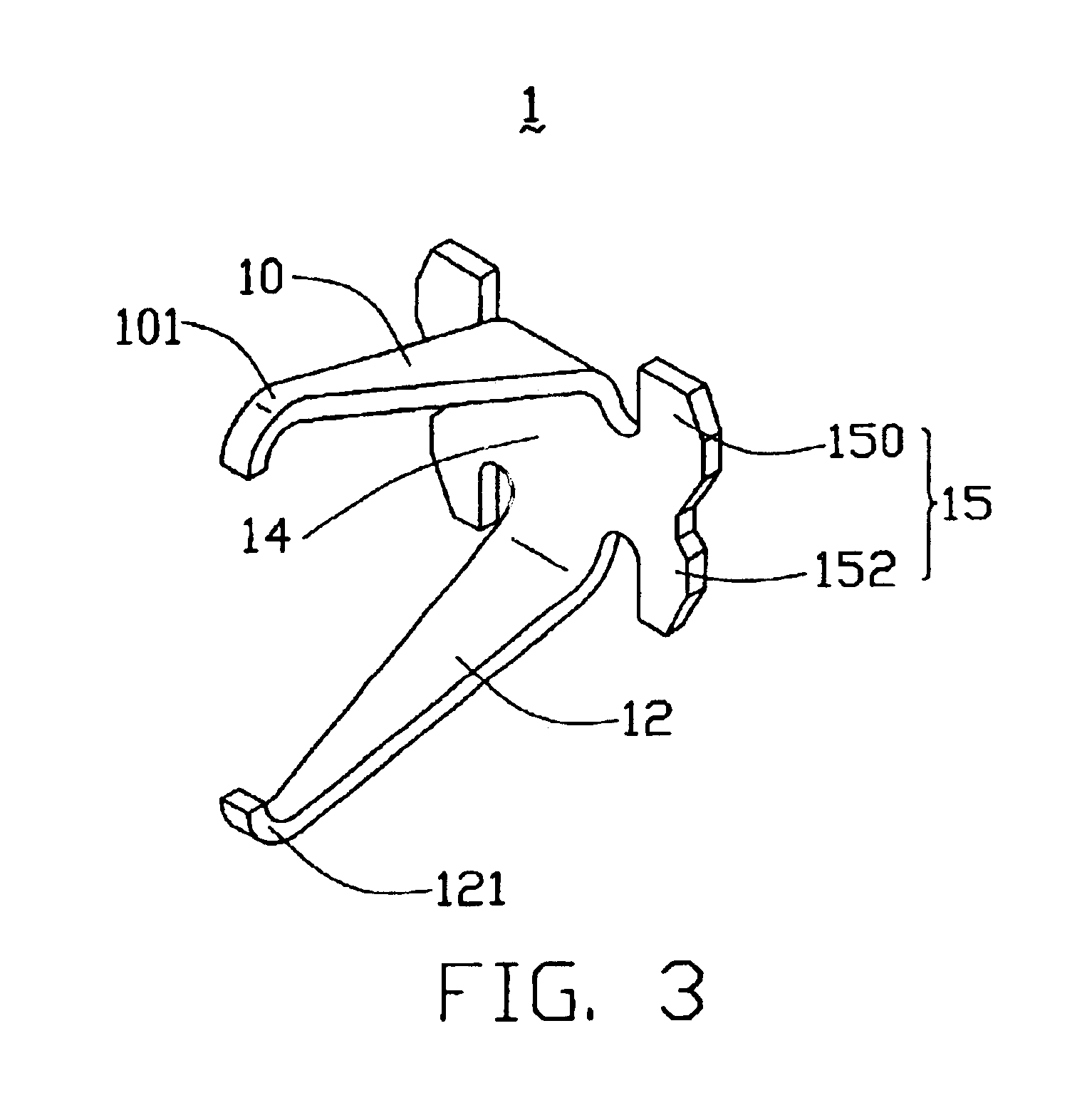
Referring particularly to FIG. 3, each terminal 1 is stamped from a sheet of conductive metallic material, and has a generally C-shaped profile. The terminal 1 comprises a connection portion 14. An upper section and a lower section of the connection portion 14 are bifurcated respectively by a first spring arm 10 and a second spring arm 12. A pair of opposite lateral retention portions 15 is thereby formed on the connection portion 14. The first spring arm 10 is generally convex and tapered, and extends upwardly and forwardly from the up...


PUM


Abstract

An LGA electrical connector (3) includes a housing (2) defining a plurality of passageways (20) therein, and a plurality of terminals (1) received the corresponding passageways. Each passageway comprises a narrow first passage (201) and a broad second passage (202). The first passage has two stepped sidewalls each with a first sidewall (2010) and a second sidewall (2012). A space between the opposite first sidewalls is greater than that between the opposite second sidewalls. Each terminal comprises two retention portions (15). Each retention portion itself is separated, and forms a broad first interference portion (150) and a narrow second interference portion (152). The first interference portion of the terminal interferentially engages with the first sidewall of the passageway. The second interference portion of the terminal interferentially engages with the second sidewall of the passageway. Thus, the terminal can be securely received in the passageway of the housing.

Description

BACKGROUND OF THE INVENTION1. Field of the InventionThe present invention relates to an electrical connector for electrically connecting an electronic package such as a land grid array (LGA) chip with a circuit substrate such as a printed circuit board (PCB), and particularly to an electrical connector with terminals each having a plurality of interference blocks.2. Description of the Prior ArtLand grid array (LGA) connectors are widely used in personal computer (PC) systems to electrically connect LGA chips with PCBs. An LGA connector comprises a multiplicity of terminals arranged in a housing in a rectangular array. Each terminal has a first contact portion soldered to a PCB, and a second contact portion depressed by and engaging with a corresponding contact pad of an LGA chip. Thus the LGA chip and the PCB are electrically connected by the connector.U.S. Pat. Nos. 5,653,598 and 6,176,707 and Taiwan Pat. No. 501318 each disclose a conventional LGA electrical connector. Referring t...

Claims


Application Information

Patent Timeline
IPC IPC(8): H05K7/10H01R13/41H01R13/40H01R13/24H01R13/22
CPCH01R13/2435H01R12/52H05K7/1069H01R13/41H01R12/714H01R12/7082
Inventor LIAO, FANG-JWUSZU, MING-LUN
Owner HON HAI PRECISION IND CO LTD
Features
  • Generate Ideas
  • Intellectual Property
  • Life Sciences
  • Materials
  • Tech Scout
  • Unparalleled Data Quality
  • Higher Quality Content
  • 60% Fewer Hallucinations
Learn More