Rotary connector that prevents excessive temperature increase generated in a flexible cable
- Summary
- Abstract
- Description
- Claims
- Application Information
AI Technical Summary
Benefits of technology
Problems solved by technology
Method used
Image

Examples
first embodiment
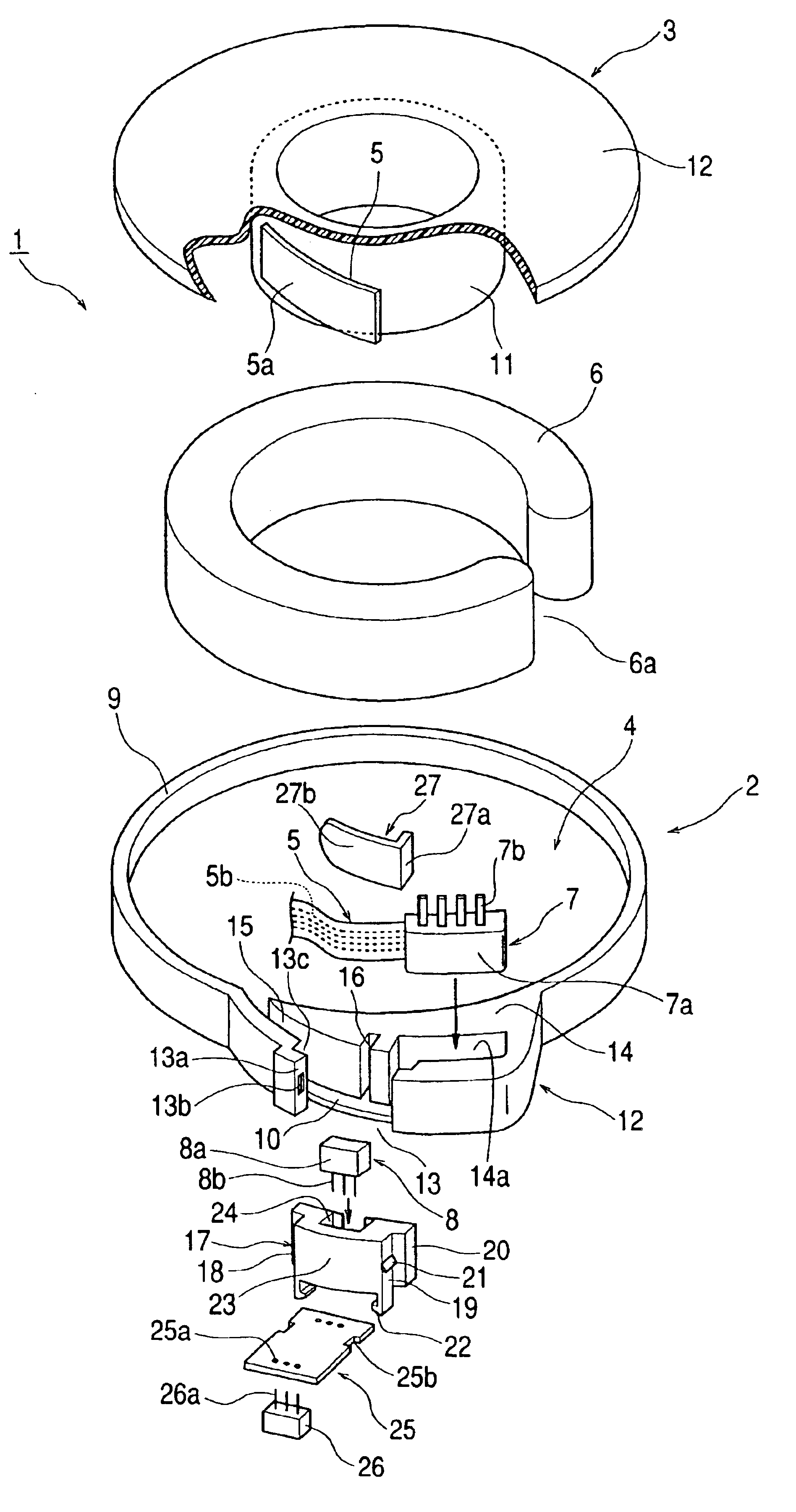
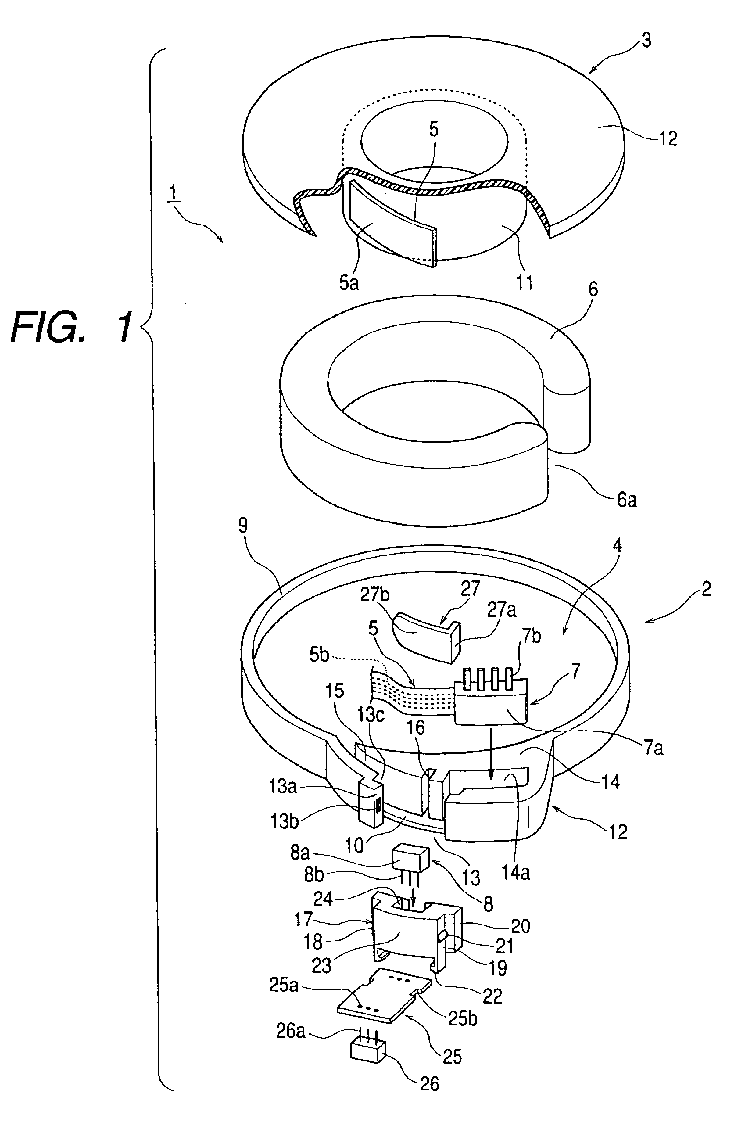
A rotary connector in accordance with the present invention will be explained below with reference to the accompanying drawings. FIG. 1 is an exploded perspective view of a rotary connector in accordance with the present invention.
Referring to FIG. 1, the overall construction of a rotary connector 1 explained hereinafter includes: a stationary housing 2; a movable housing 3 connected to the stationary housing 2 so as to be rotatable relatively- thereto; a flexible cable 5 as a flat cable housed within a housing section 4 formed between the stationary and movable housings 2, 3; a movable structure 6 rotatably disposed between the stationary and movable housings 2, 3; a lead block 7 connected to the flexible cable 5; and a temperature sensor 8 as temperature detection means for detecting temperature of the flexible cable 5 while exposing the body of the temperature sensor within the housing section 4.
The stationary housing 2 includes a cylinder-shaped outer cylindrical portion 9, a ci...
third embodiment
Next, the connection status between a flexible cable and a lead block of the rotary connector in accordance with the present invention will be explained.
As shown in FIGS. 8 and 9, the construction of a flexible cable 34 is similar to that of the flexible cable 5 employed in the previously described second embodiment and therefore, the explanation associated with the flexible cable is omitted.
As for the construction of a lead block 35, as shown in FIGS. 8 and 9, the construction thereof different from that of the lead block 7 employed in the previously described second embodiment will be explained.
Different from the base section 32 employed in the second embodiment, a base section 36 of the lead block 35 has an approximately rectangular recess 35c therein on the rear end side thereof (lower side of FIG. 9 when viewing the paper from a direction vertical to the paper). Within the recess 35c is provided an approximately rectangular temperature sensor 37 as temperature detection means, ...
PUM
 Abstract
Description
Claims
Application Information