Inflatable surface including a plurality of nozzles

a plurality of nozzles and inflatable surface technology, applied in the direction of vehicular safety arrangments, vehicle components, pedestrian/occupant safety arrangements, etc., can solve the problems of pre-stressed portions failing, occupants being thrown against the windows, doors and side walls of the vehicle, etc., and achieve the effect of minimal gas generation

Inactive Publication Date: 2005-01-25
AUTOLIV ASP INC
View PDF10 Cites 44 Cited by
  • Summary
  • Abstract
  • Description
  • Claims
  • Application Information

AI Technical Summary

Benefits of technology

In one embodiment, a curtain airbag inflator includes one or more nozzle arrays in a face of the inflator. The curtain airbag may include sectioned portions of the airbag which form protection zones to inflate and protect an occupant. The nozzle arrays may be positioned such that each nozzle array corresponds to a protection zone of the curtain airbag. In this manner, the protection zones may be quickly inflated and minimal gas generant may be required.

Problems solved by technology

In these accidents, the occupant may be thrown against the windows, doors and side-walls of the vehicle.
Spherical inflation of the airbag may be problematic depending on the shape of the airbag.
However, in a curtain airbag, spherical inflation, or inflation from a single point source, may cause several problems including bag slap (referring to the un-inflated portion of an airbag striking an occupant while inflating).
Spherical inflation may cause delayed inflation of certain airbag portions, and / or pre-stress portions of the airbag in the vicinity of the point inflation source such that the pre-stressed portions fail during operation of the airbag.
However, using a diffuser impedes the flow of exhaust gas.
In addition, because diffusers are generally separate components, production, assembly and material costs for the airbag may be increased.
In addition, with an additional part, the diffuser, the potential for defective parts, and / or assembly errors increases.
This exposure may cause interference with the exit ports and / or diffuser holes.
For example, condensation within the inflator may cause the gas generant to break up or become neutralized.
In addition, because most conventional inflators are limited to spherical inflation, certain limitations are imposed on how the airbag modules are packaged and where airbag modules are located within a vehicle.
For example, due to space requirements and spherical inflation, airbag modules are generally not located in a door side panel.

Method used


Image

  • Inflatable surface including a plurality of nozzles
  • Inflatable surface including a plurality of nozzles
  • Inflatable surface including a plurality of nozzles

Examples


Embodiment Construction

The present invention can be better understood with reference to the drawings where like parts are designated with like numerals throughout.

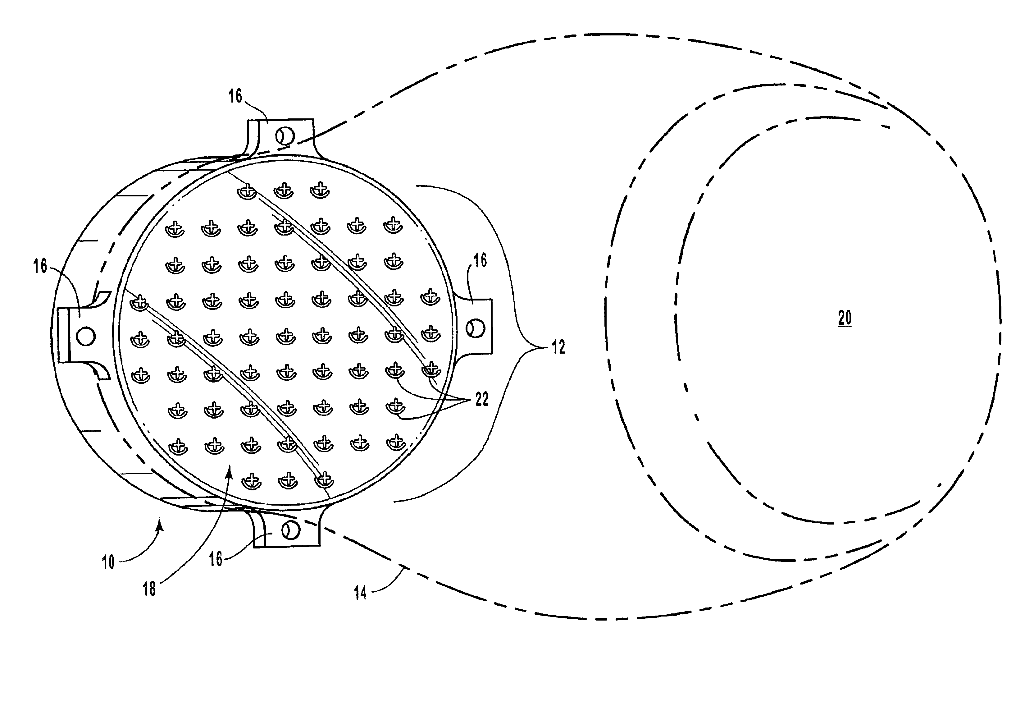
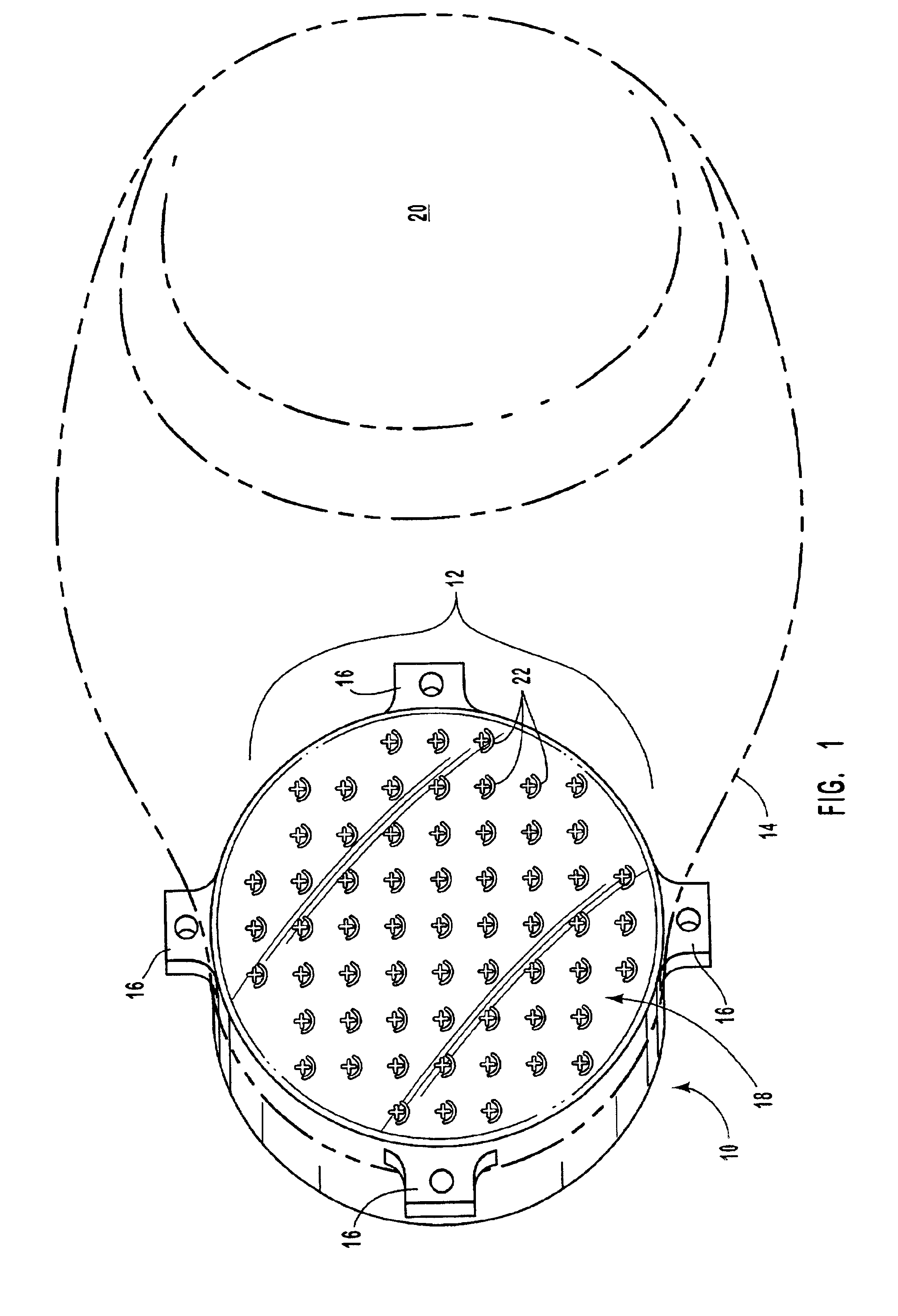
FIG. 1 is a perspective front view illustrating one embodiment of an inflator 10 including a nozzle array 12 according to the present invention. The inflator 10 is preferably in fluid communication with an airbag 14. The airbag 14 is illustrated in dashed lines to indicate the shape of the airbag 14 once inflated.

In certain embodiments, the inflator 10 is configured to house a very rapid production of exhaust gas without breaking apart. In addition, the inflator 10 is preferably light weight. Therefore, the inflator 10 is preferably made from a sturdy, rigid material such as metal, ceramic, hard plastic, or other similar material.

The inflator 10 includes one or more mounting tabs 16. The mounting tabs 16 are generally used to secure the inflator 10 to an airbag module housing (not shown), vehicle frame, or other vehicle component. The mounting t...


PUM


Abstract

An airbag inflator housing is disclosed that provides a multi-dimensional inflation surface. The housing may include a back wall, a front wall, and at least one side wall connecting the front wall to the back wall to enclose a volume within the housing. A nozzle array may be integrated with the front wall. The nozzle array may include a plurality of pre-formed and sealed nozzles. The nozzles may be arranged according to a two-dimensional array to provide an inflation surface to inflate a connected airbag. The nozzles may be formed using MEMS processes to provide very small and precise nozzles.

Description

BACKGROUND OF THE INVENTION1. The Field of the InventionThe present invention relates to vehicle airbag systems. More specifically, the invention relates to an array of nozzles integrated with an inflator housing for even distribution of exhaust gas generated by the inflator.2. Technical BackgroundInflatable airbags are well accepted for use in motor vehicles and have been credited with preventing numerous deaths and injuries. Some statistics estimate that frontal airbags reduce the fatalities in head-on collisions by 25% among drivers using seat belts and by more than 30% among unbelted drivers. Statistics further suggest that with a combination of seat belt and airbag, serious chest injuries in frontal collisions can be reduced by 65% and serious head injuries by up to 75%. Airbag use presents clear benefits. Airbags are generally required in most all new vehicles.A modern airbag apparatus may include an electronic control unit (ECU) and one or more airbag modules. The ECU include...

Claims


Application Information

Patent Timeline
Patent Type & Authority Patents(United States)
IPC IPC(8): B60R21/26B60R21/264
CPCB60R21/261B60R21/2644B60R2021/2617
Inventor RINK, KARL K.GREEN, DAVID J.
Owner AUTOLIV ASP INC
Why Eureka
Try Eureka