Knee prosthesis

a prosthesis and knee technology, applied in the field of knee prosthesis, can solve the problems of increased plastics wear, pain and morbidity, and inability to reliably reproduce presently

Inactive Publication Date: 2005-01-25
MCMINN DEREK JAMES WALLACE
View PDF25 Cites 139 Cited by
  • Summary
  • Abstract
  • Description
  • Claims
  • Application Information

AI Technical Summary

Benefits of technology

The invention provides an improved knee prosthesis which reduces or obviates the disadvantages of the prior art referred to in the above section.

Problems solved by technology

This is not presently reliably reproduced in knee replacement design, and lateral patella maltracking is a common cause of pain and morbidity.
This is undesirable in producing a reduced area of contact between the lateral femoral condyle and the polyethylene articulating surface, with the potential for increased plastics wear.
Any attempt by a designer to angulate the patella groove will have serious detrimental effects.

Method used


Image

  • Knee prosthesis
  • Knee prosthesis
  • Knee prosthesis

Examples


Embodiment Construction

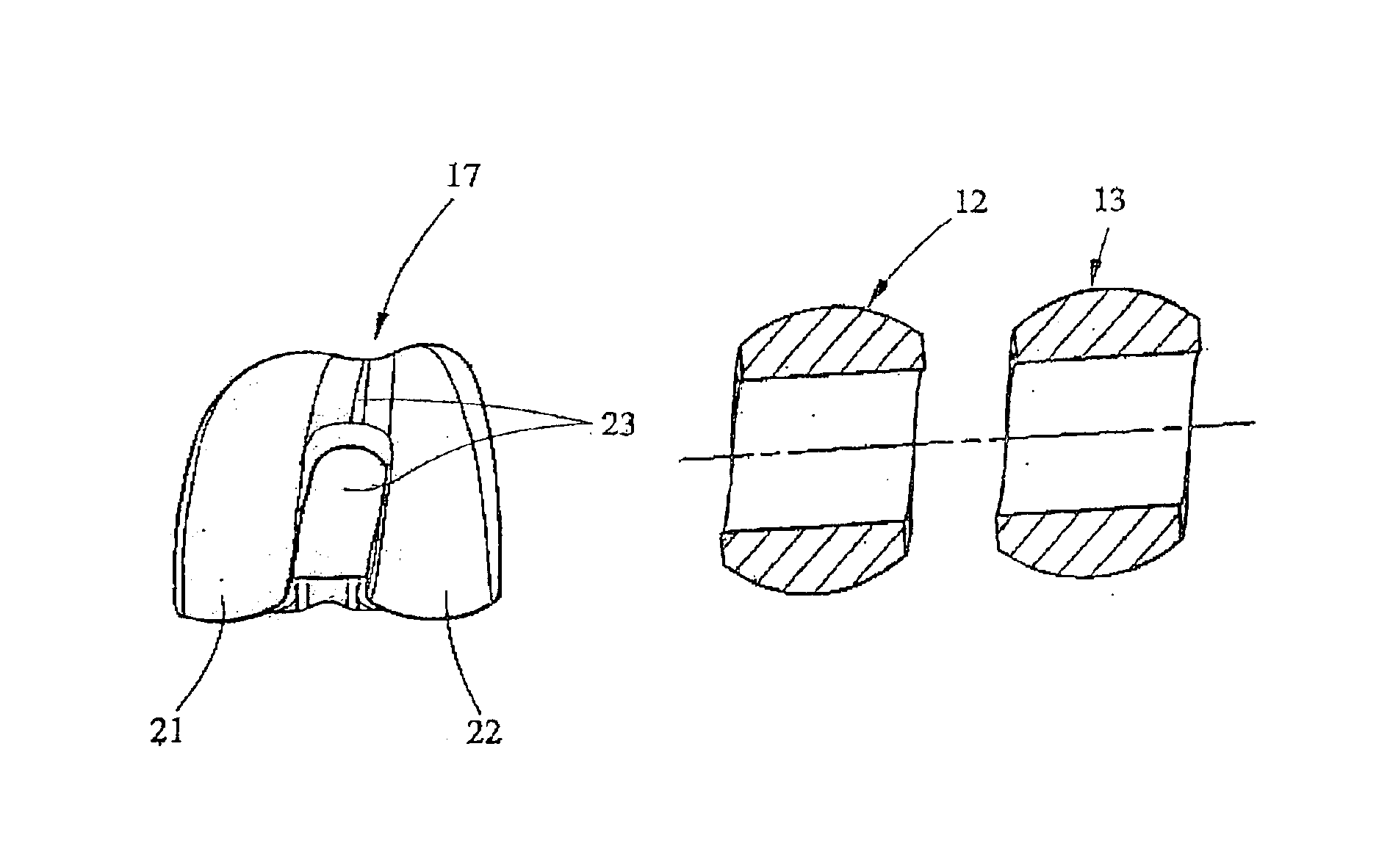
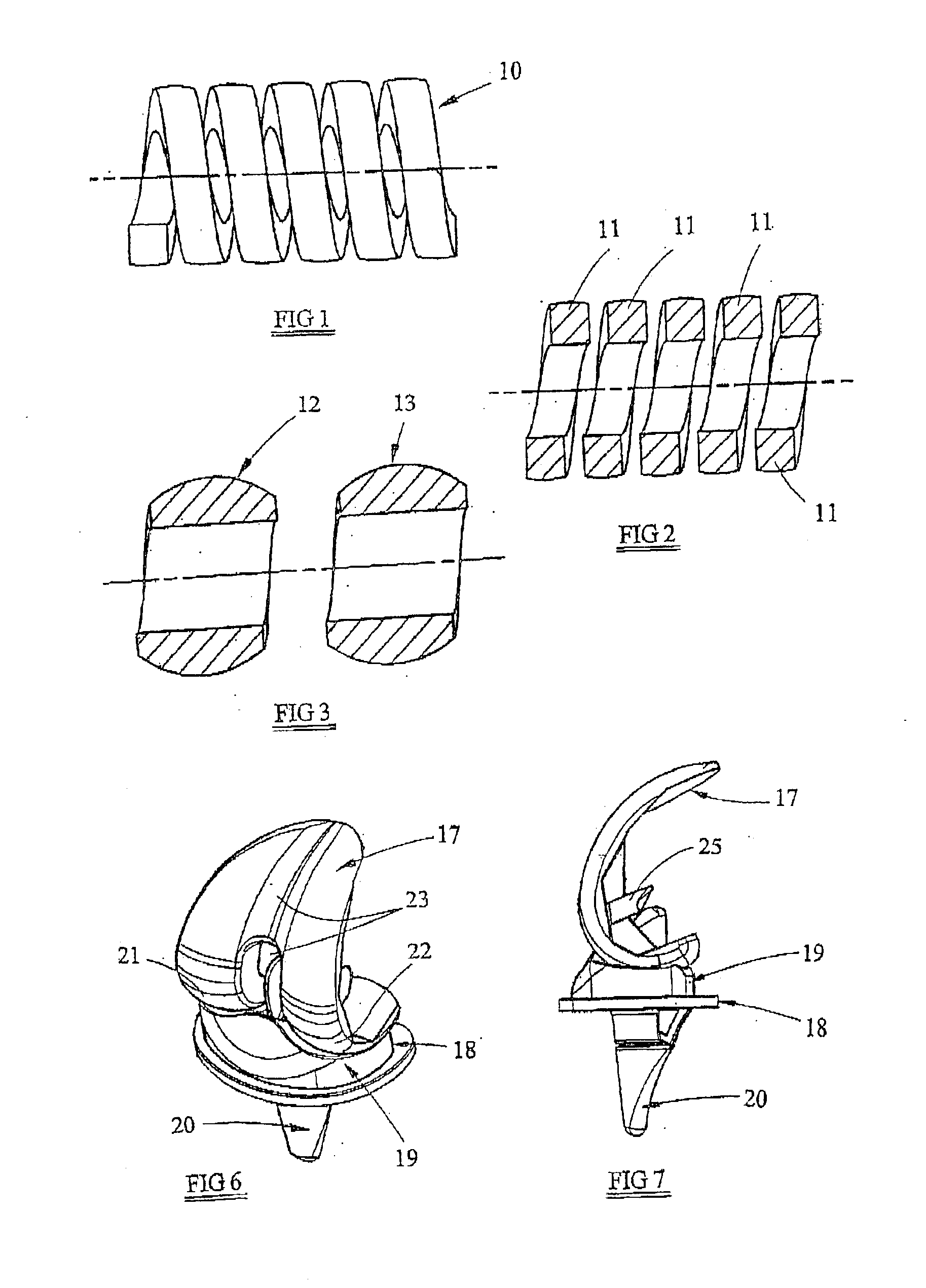
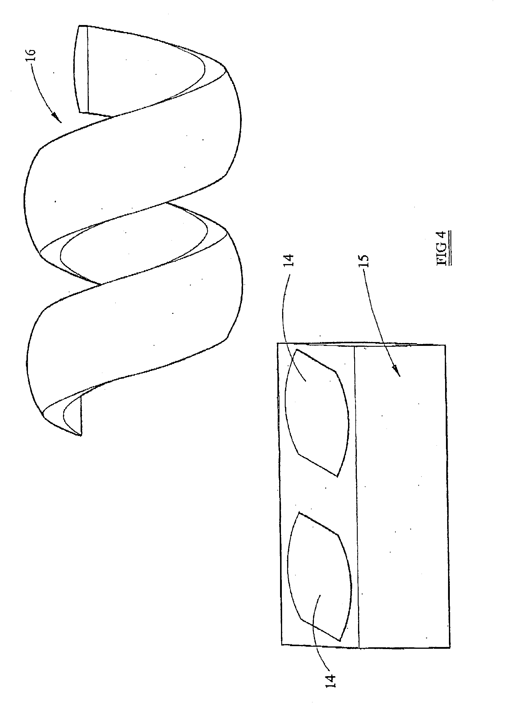
As will be described with the knee prosthesis shown in FIGS. 5 to 12 and 24 and 25, the invention of the present application basically relates to the shaping of the medial and lateral condyles and the corresponding engagement surfaces of a tibial bearing insert, with which the condyles engage, as matching part-helical, for example in the manner of a screw-thread and associated corresponding nut engaged therewith. Although it would be possible to provide condyles in the form of the threads cut in the nut, with the threads on the screw being provided by the bearing component, it is preferred, as will be described, that the screw-threads, i.e. the male part of the thread will be defined by the condyles, with the bearing component being matchingly grooved in the nature of the threads cut in the nut. By this means, as will be more fully explained below, congruent contact can be made between the femoral component and the tibial bearing insert of the prosthesis both in the extended state o...


PUM


Abstract

A knee prosthesis comprises a femoral component, a tibial component and a bearing component therebetween. The femoral component defines medial and lateral condylar surfaces which are in the form of respective parts of a common helix, and the bearing component has respective surfaces matching the condylar surfaces. Accordingly a patella groove in the femoral component is laterally displaced, and on flexion of the knee, in use, from an extended position there is a lateral translatory movement of the femur. Congruent contact between the femoral component and the bearing component is maintained through at least 60° of flexion of the knee from an extended position.

Description

FIELD OF THE INVENTIONThis invention relates to a knee prosthesis for fitting to a patient as a replacement knee joint.DESCRIPTION OF THE RELATED ARTIn a normal knee, the groove on the femur for the patella is laterally displaced with respect to the mid point of the femur, this lateral displacement being of the order of 5 m.m. In addition to being laterally displaced, the patella groove on the femur is laterally angulated by 7° with respect to the distal femur and knee joint.In the normal knee therefore as it flexes, the patella articulates in the patella groove on the femur. Clearly it is thus important in knee replacement design to reproduce the natural position of the patella groove on the prosthetic femoral component. This is not presently reliably reproduced in knee replacement design, and lateral patella maltracking is a common cause of pain and morbidity. In one known design, part of the lateral femoral condyle prosthesis is removed to accommodate such lateral displacement of...

Claims


Application Information

Patent Timeline
Patent Type & Authority Patents(United States)
IPC IPC(8): A61F2/38
CPCA61F2/3886A61F2/3877
Inventor MCMINN, DEREK JAMES WALLACE
Owner MCMINN DEREK JAMES WALLACE
Why Eureka
Try Eureka