Transmitter-receiver control system for an actuator and method

a technology of actuator and receiver, applied in the field of remote control of actuators, can solve the problem that the receiver no longer responds to the transmitter with the old code, and achieve the effect of faster actuator response time and system efficiency

Inactive Publication Date: 2005-01-25
NORTEK SECURITY & CONTROL LLC
View PDF7 Cites 8 Cited by
  • Summary
  • Abstract
  • Description
  • Claims
  • Application Information

AI Technical Summary

Benefits of technology

It should be appreciated, therefore, that the present control system may activate multiple transmitters having different transmitter IDs without facing the risk of disabling previously activated transmitters. Because the present control system does not store the actual transmitter codes in the memory locations, there is no overriding of previously stored transmitter codes which causes the previously activated transmitters to be disabled. Instead, the present control system uses the transmitter IDs as memory addresses, and sets valid bits in the memory addresses for activating the transmitters. Each transmitter is coded with a different transmitter identifier. Thus, each of the different transmitter identifiers map to a different memory location.
It should also be appreciated that the direct mapping of transmitter IDs to memory locations allows the system to be more efficient. Instead of invoking a search algorithm for searching each memory location for a match of a transmitter ID received during a read mode, the use of the transmitter ID as a memory address allows a direct mapping into an appropriate memory location. Thus, under the present system, only one memory location needs to be examined for determining whether the received transmitter ID is valid.
The present system and method therefore allows for faster actuator response time which becomes more significant as the number of possible transmitters capable of interacting with the actuator increases. Under the prior art, as the number of the possible transmitters goes up, so does the number of memory locations that need to be searched. The search time then starts to become a factor in the actuator response time.

Problems solved by technology

One disadvantage of the current technology is that once all the memory locations have been filled with codes, the learning of a new code causes the new code to overwrite a previously stored old code, causing the receiver to no longer respond to a transmitter with the old code.

Method used


Image

  • Transmitter-receiver control system for an actuator and method
  • Transmitter-receiver control system for an actuator and method
  • Transmitter-receiver control system for an actuator and method

Examples


Embodiment Construction

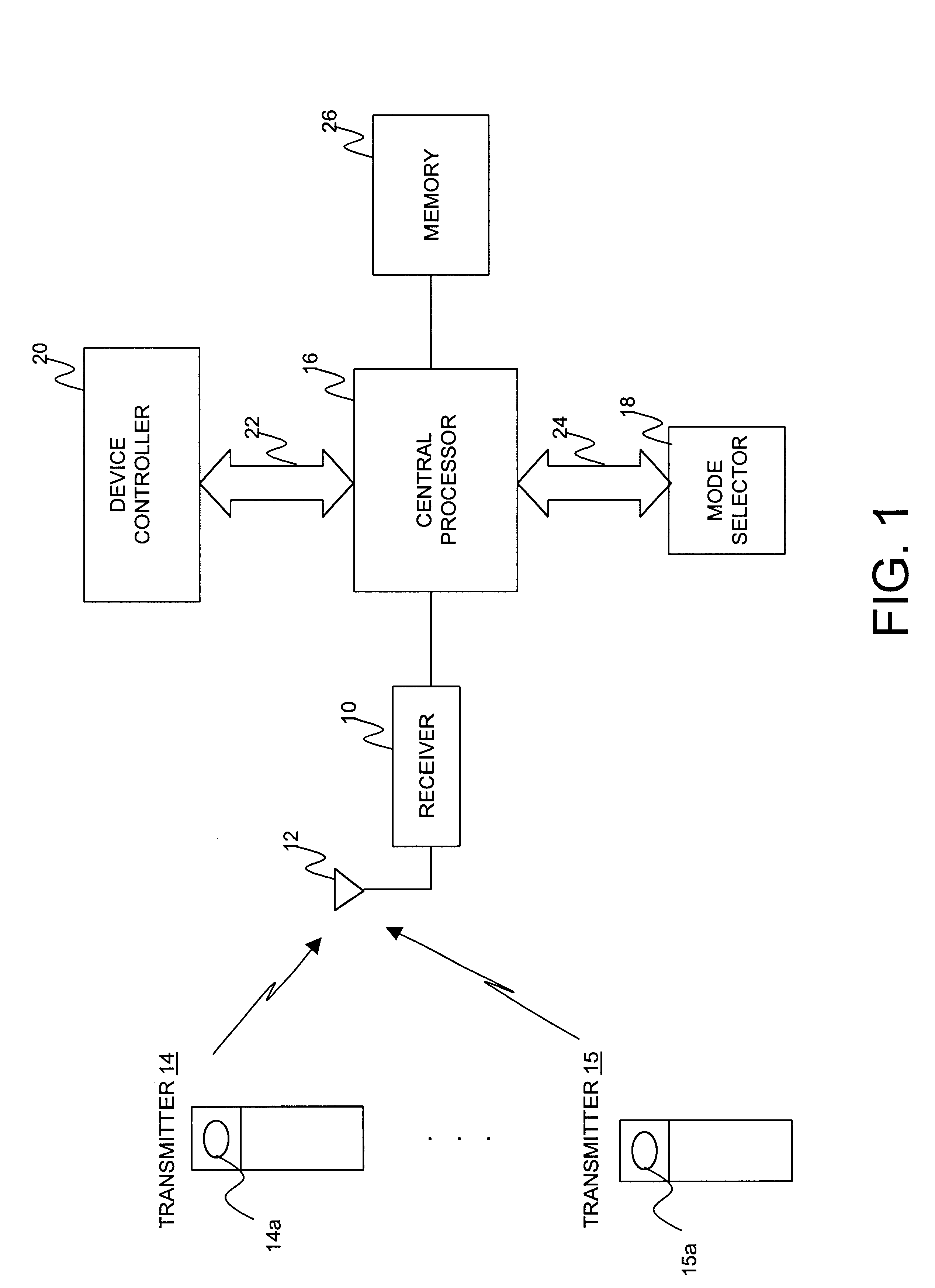
FIG. 1 is a schematic block diagram of a control system for an actuator according to one embodiment of the invention. The actuator may include a garage door opener, gate opener, window blinds opener, security alarm trigger, light energizer, or any other apparatus capable of triggering action on a device being controlled.

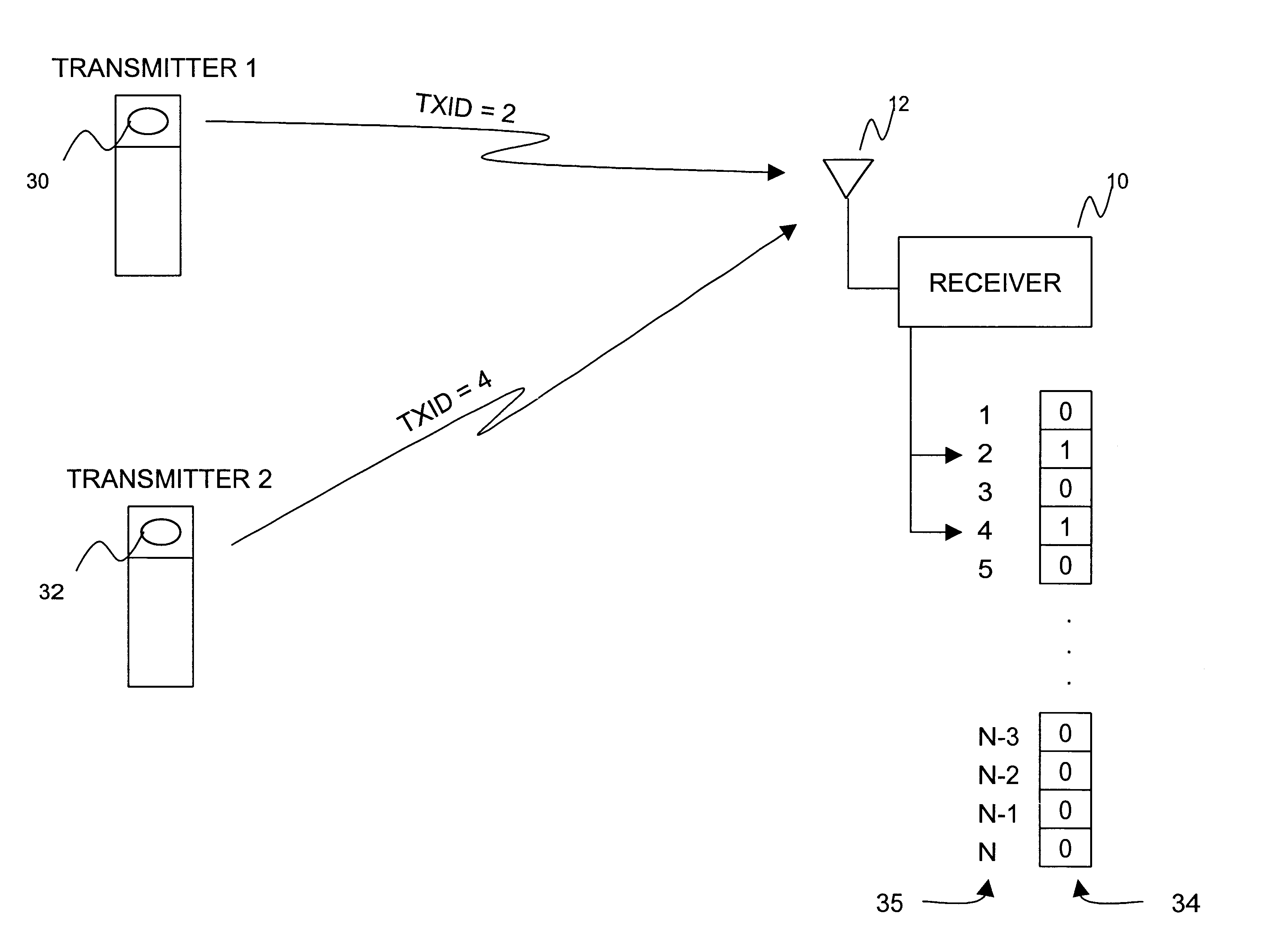
The system preferably includes a receiver 10 having an antenna 12 for receiving signals transmitted by transmitters 14, 15. The transmitters 14, 15 and the receiver 10 respectively transmit and receive RF signals. However, infrared signals and other type of signals conventional in the art may also be exchanged between the transmitters and the receiver.

Each transmitter 14, 15 preferably includes a chip encoded with a unique transmitter ID which is preferably factory-determined at the time of making of the transmitter. Each transmitter 14, 15 further includes an actuation button 14a, 15a for operating the transmitter.

The receiver 10 is coupled to a central processor 16...


PUM


Abstract

A control system for an actuator used to actuate a device. A receiver in the control system receives different transmitter identifiers from multiple transmitters. A central processor coupled to the receiver uses a received transmitter identifier as the address of a memory location. If the control system is set to a write mode when the transmitter identifier is received, a valid bit is set in the addressed memory location to indicate that the transmitter identifier is valid. If the control system is set to read mode when the transmitter identifier is received, the addressed memory location is examined to determine if a valid bit has been set. If the valid bit has been set, the central processor transmits a signal for actuating the device.

Description

FIELD OF THE INVENTIONThis invention relates generally to remotely controlled actuators, and more particularly to actuators capable of being energized by multiple transmitters.BACKGROUND OF THE INVENTIONRemotely controlled actuators such as, for example, garage door openers are known in the art. These actuators may be activated by one or more transmitters where each transmitter is associated with a unique transmitter code. In order for an actuator to respond to a particular transmitter, a receiver associated with the actuator must generally learn the code of the transmitting transmitter. The learning is generally accomplished by storing the transmitter code in a memory associated with the receiver.Current technology allows a garage door opener to respond to multiple transmitters with multiple codes by storing the multiple codes in a receiver-memory that has a limited number of memory locations. When a code to be learned is received by the receiver, a memory location is identified vi...

Claims


Application Information

Patent Timeline
Patent Type & Authority Patents(United States)
IPC IPC(8): B60R25/00G07C9/00
CPCG07C9/00182G07C2009/00928G07C2009/00793
Inventor STOTTLEMYRE, DANKAHN, PAUL
Owner NORTEK SECURITY & CONTROL LLC
Why Eureka
Try Eureka