Incline-adjustable air mattress

a technology of air mattress and incline, which is applied in the direction of rigid mattresses, beds, rigid tables, etc., can solve the problems of not disclosing a new incline-adjustable air mattress, and achieve the effects of reducing the incidence of gastro-esophagus influx, pain and discomfort, and being easy to set up and us

Inactive Publication Date: 2005-02-01
BARNES CHRISTOPHER A
View PDF11 Cites 58 Cited by
  • Summary
  • Abstract
  • Description
  • Claims
  • Application Information

AI Technical Summary

Benefits of technology

Still yet another object of the present invention is to provide a new incline-adjustable air mattress that is easy and convenient to set up and use.
Even still another object of the present invention is to provide a new incline-adjustable air mattress that reduces the incidence of gastro-esophagus influx, respiratory conditions, and pain and discomfort following surgery or injury.

Problems solved by technology

While these devices fulfill their respective, particular objectives and requirements, the aforementioned patents do not disclose a new incline-adjustable air mattress.

Method used


Image

  • Incline-adjustable air mattress
  • Incline-adjustable air mattress
  • Incline-adjustable air mattress

Examples


Embodiment Construction

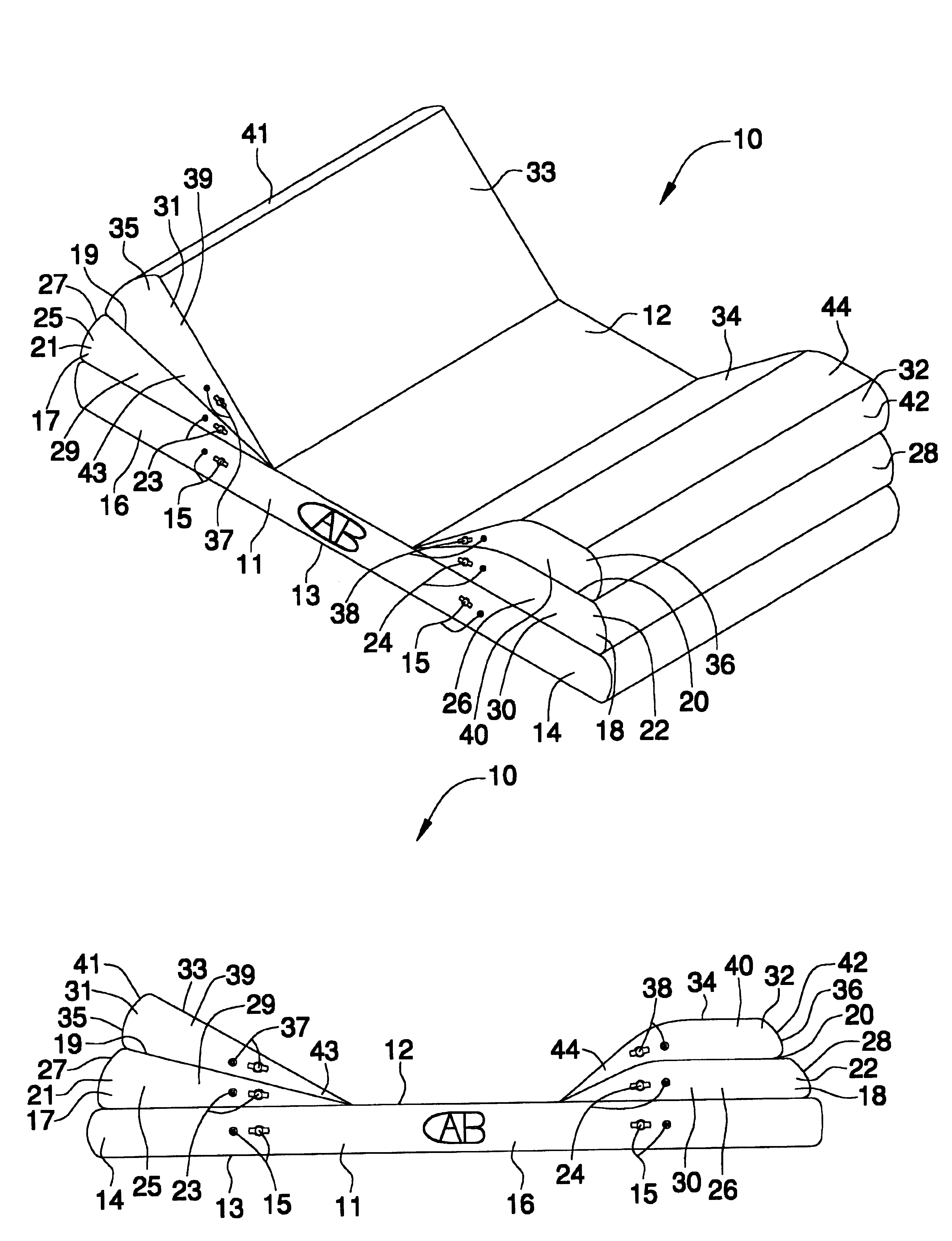
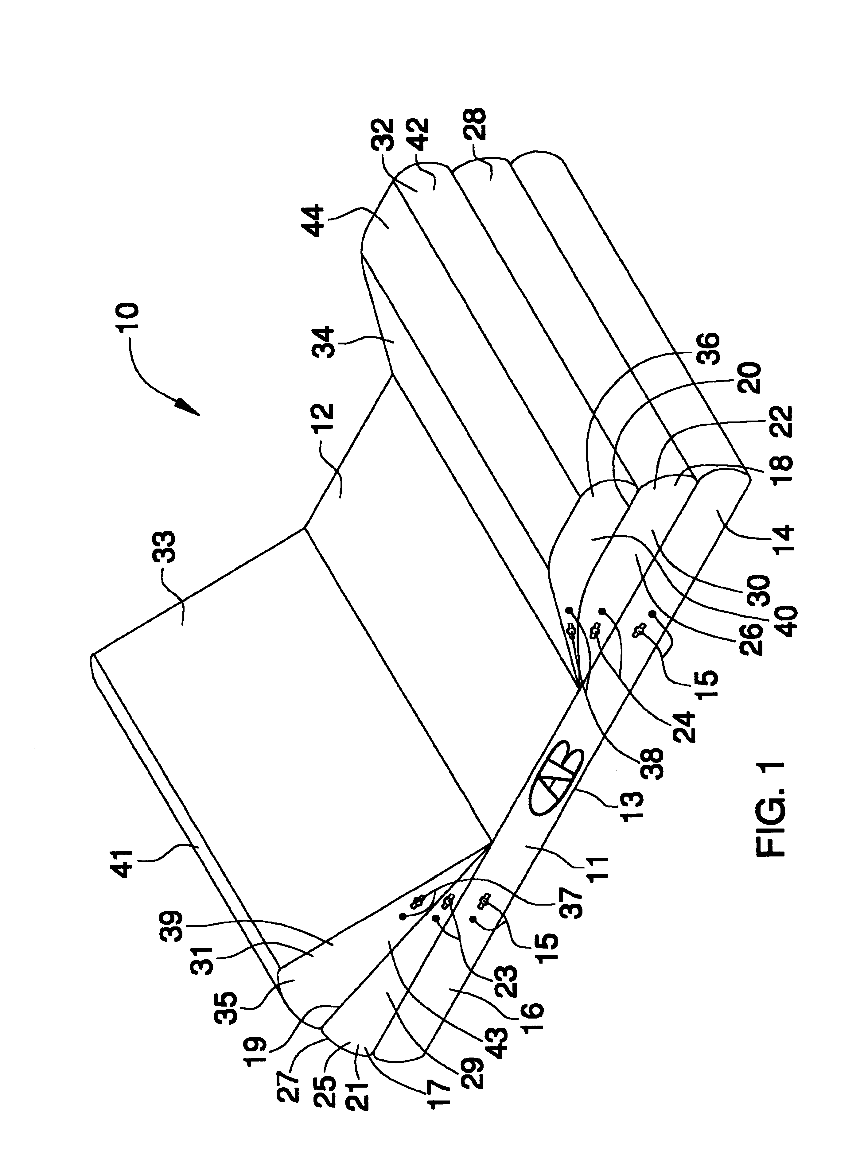
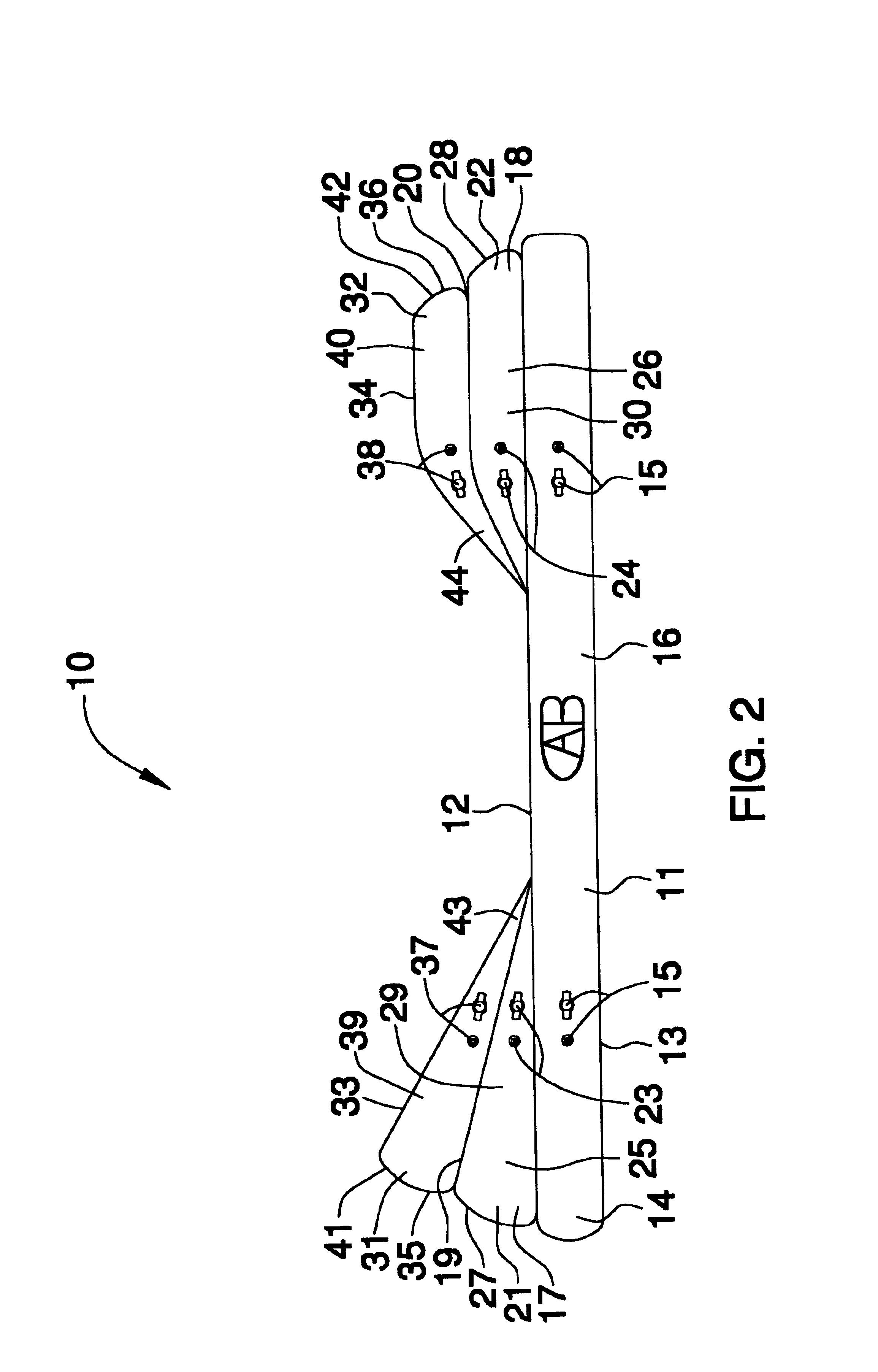
With reference now to the drawings, and in particular to FIGS. 1 through 2 thereof, a new incline-adjustable air mattress embodying the principles and concepts of the present invention and generally designated by the reference numeral 10 will be described.

As best illustrated in FIGS. 1 through 2, the incline-adjustable air mattress 10 generally comprises a base section 11 having top, bottom and perimeter walls 12-14, and also having air valve members 15 being conventionally disposed in the perimeter wall 14, and further having an air chamber 16 being disposed between the top, bottom, and perimeter walls 12-14. The perimeter wall of the base section is generally an endless strip being disposed along edges of the top and bottom walls and has a width which is generally uniform throughout.

Intermediate sections 17, 18 are disposed upon and securely connected to the base section 11, and include a head intermediate section 17 being disposed upon a front portion of the base section 11, and ...


PUM


Abstract

An incline-adjustable air mattress for elevating a user's head and legs relative to the user's torso. The incline-adjustable air mattress includes a base section having top, bottom and perimeter walls, and also having air valve members being disposed in the perimeter wall, and further having an air chamber disposed between the top, bottom, and perimeter walls; and also includes intermediate sections being disposed upon and connected to the base section; and further includes upper sections being disposed upon and connected to the intermediate sections.

Description

BACKGROUND OF THE INVENTION1. Field of the InventionThe present invention relates to incline air mattresses and more particularly pertains to a new incline-adjustable air mattress for elevating a user's head and legs relative to the user's torso.2. Description of the Prior ArtThe use of incline air mattresses is known in the prior art. More specifically, incline air mattresses heretofore devised and utilized are known to consist basically of familiar, expected and obvious structural configurations, notwithstanding the myriad of designs encompassed by the crowded prior art which have been developed for the fulfillment of countless objectives and requirements.Known prior art includes U.S. Pat. No. 5,170,522; U.S. Pat. No. 5,577,278; U.S. Pat. No. 4,639,960; U.S. Pat. No. 5,311,625; U.S. Pat. No. 5,345,630; and U.S. Patent No. Des. 359,189.While these devices fulfill their respective, particular objectives and requirements, the aforementioned patents do not disclose a new incline-adjus...

Claims


Application Information

Patent Timeline
Patent Type & Authority Patents(United States)
IPC IPC(8): A47C20/04A47C20/00A47C27/10
CPCA47C20/048A47C27/10A47C27/081
Inventor BARNES, CHRISTOPHER A.
Owner BARNES CHRISTOPHER A
Why Eureka
Try Eureka