Counter-track joint having identically orientated opposed pairs of tracks

a counter-track joint and opposite track technology, applied in mechanical equipment, yielding couplings, rotary machine parts, etc., can solve problems such as joint control, and achieve the effect of improving control conditions and improving control characteristics

Inactive Publication Date: 2005-02-01
GKN AUTOMOTIVE GMBH
View PDF7 Cites 28 Cited by
  • Summary
  • Abstract
  • Description
  • Claims
  • Application Information

AI Technical Summary

Benefits of technology

The present invention provides a counter-track joint with improved control characteristics. The counter-track joint includes first pairs of tracks positioned radially opposite other first pairs of tracks, and second pairs of tracks positioned radially opposite other second pairs of tracks. More particularly, the first pairs of tracks and second pairs of tracks are arranged so as to alternate across the circumference of the joint. In one embodiment, a joint with eight uniformly circumferentially distributed pairs of tracks is disclosed. Other joint embodiments include twelve or sixteen pairs of tracks. An inventive joint is characterised by resulting control forces which constantly deviate from zero, and which are applied by pairs of tracks to the respective opposed pairs of balls, so that, overall, control conditions can be improved substantially. The reasons for such improved control force conditions will be explained below with reference to the drawings.

Problems solved by technology

This design has disadvantages with regard to joint control, i.e., the control force conditions at the cage.

Method used


Image

  • Counter-track joint having identically orientated opposed pairs of tracks
  • Counter-track joint having identically orientated opposed pairs of tracks
  • Counter-track joint having identically orientated opposed pairs of tracks

Examples


Embodiment Construction

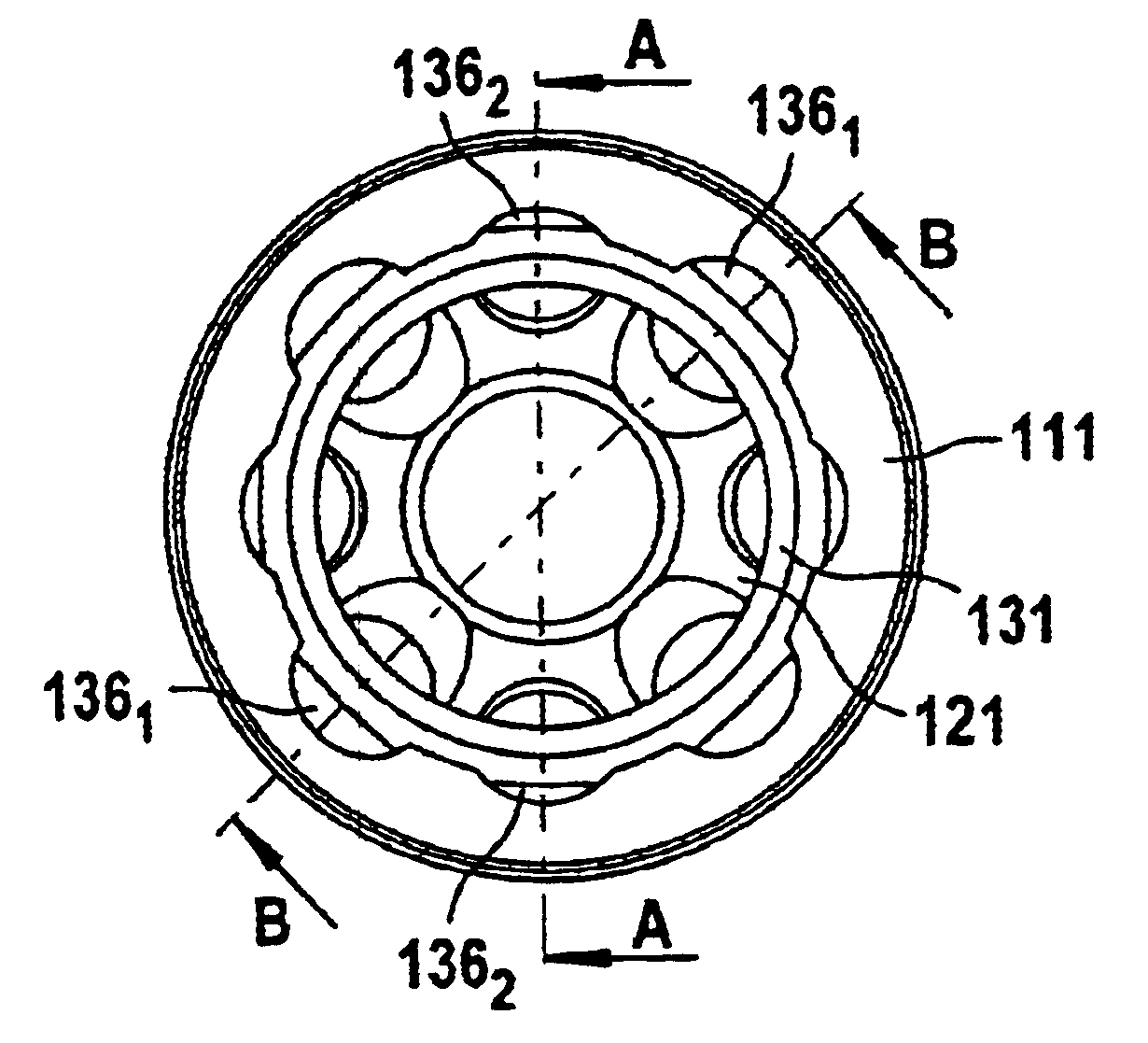
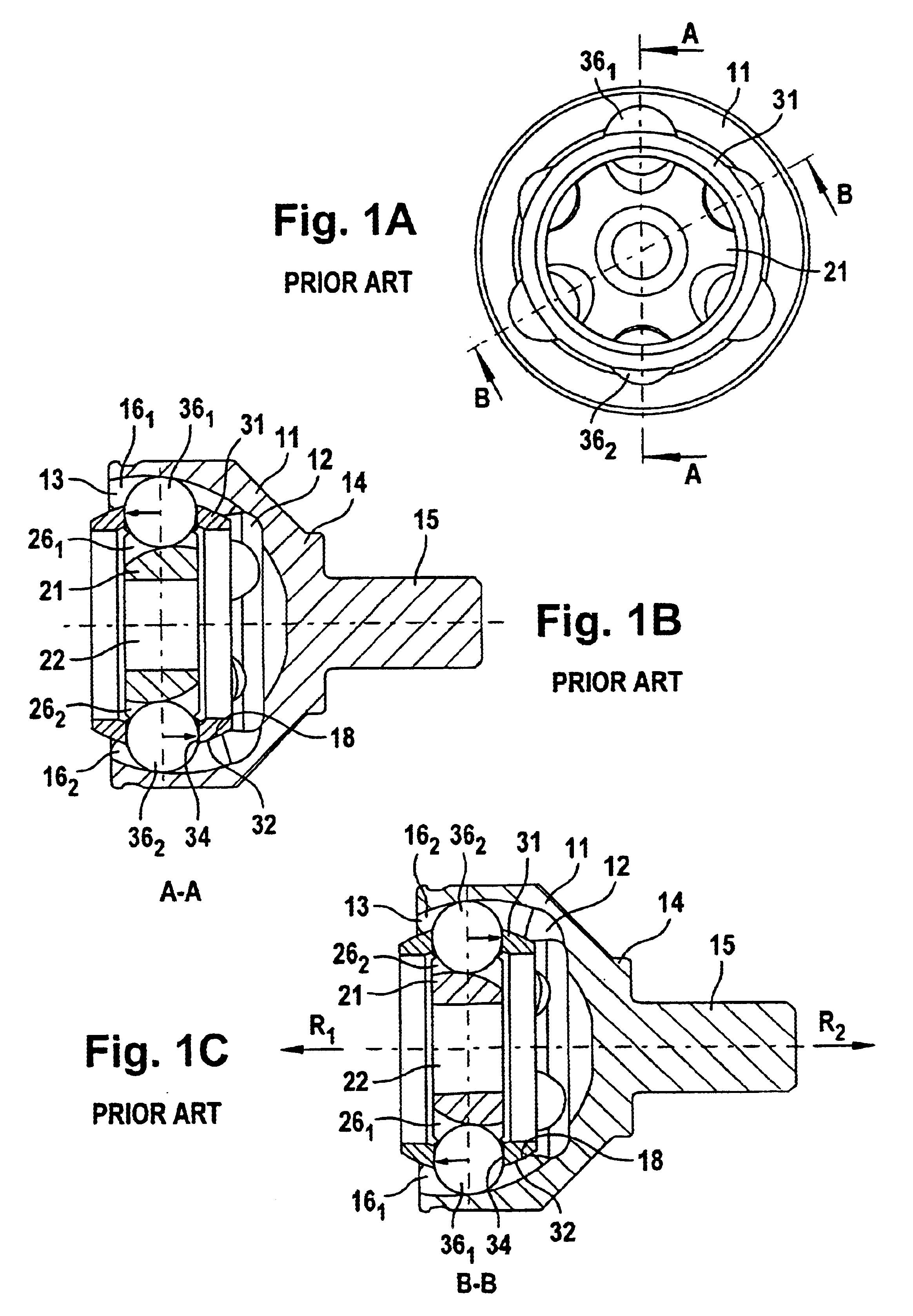
The illustrations of FIG. 1 will be described jointly below. An outer joint part 11 comprises an interior 12 with an aperture 13 and an opposed base 14. A connecting journal 15 is formed on to the base 14. In the interior 12, there is accommodated an inner joint part 21 with an inner aperture 22 for inserting a shaft journal. A ball cage 31 is arranged between the outer joint part 11 and the inner joint part 21. The joint comprises first outer tracks 161 and first inner tracks 261 which diverge from one another when viewed in a first direction R1 which runs from the joint center to the aperture end of the outer joint part. Furthermore, the joint comprises second outer tracks 162 and second inner tracks 262 which diverge from one other when viewed in a second direction R2 which, when viewed from the joint center, runs towards the journal end of the outer joint part. First outer tracks 161 and first inner tracks 261 form first pairs of tracks, with second outer tracks 162 and second i...


PUM


Abstract

A constant velocity fixed ball joint in the form of a counter-track joint comprising an outer joint part with outer tracks, an inner joint part with inner tracks, torque-transmitting balls accommodated in pairs of tracks, and a ball cage with cage windows in which the balls are held in a common plane. First outer tracks and first inner tracks form first pairs of tracks which diverge from one another running in a first axial direction towards the connection end of the inner joint part and hold first balls. Second outer tracks and second inner tracks form second pairs of tracks which diverge from one another running in a second axial direction towards the connection end of the outer joint part and hold second balls. First pairs of tracks are positioned radially opposite other first pairs of tracks, and second pairs of tracks are positioned radially opposite other second pairs of tracks.

Description

TECHNICAL FIELDThe invention relates to a constant velocity fixed ball joint in the form of a counter-track joint comprising an outer joint part with outer tracks, an inner joint part with inner tracks, torque-transmitting balls accommodated in pairs of tracks consisting of outer tracks and inner tracks, and a ball cage with cage windows in which the balls are held in a common plane and guided on to the angle-bisecting plane when the joint is articulated. First outer tracks, together with first inner tracks, form first pairs of tracks which diverge from one another along a first axial direction towards the connection end of the inner joint part and hold first balls. Second outer tracks, together with second inner tracks, form second pairs of tracks which diverge from one another along a second axial direction towards the connection end of the outer joint part and hold second balls.BACKGROUND OF THE INVENTIONCounter-track joints of the above-mentioned type are advantageous in that th...

Claims


Application Information

Patent Timeline
Patent Type & Authority Patents(United States)
IPC IPC(8): F16D3/16F16D3/223
CPCF16D3/223Y10S464/906F16D2003/22306
Inventor WECKERLING, THOMASMAUCHER, STEPHANGREMMELMAIER, ANNATAUREG, HERBERT
Owner GKN AUTOMOTIVE GMBH
Why Eureka
Try Eureka