Control apparatus for ac motor

a control apparatus and motor technology, applied in the direction of motor/generator/converter stopper, dynamo-electric gear control, dynamo-electric converter control, etc., can solve the problems of cumbersome data input, generate the need for interpolation between non-continuous data, etc., to achieve high response, more accurately and more simply and conveniently set, and high torque control

Active Publication Date: 2009-06-04
HITACHI LTD
View PDF4 Cites 22 Cited by
  • Summary
  • Abstract
  • Description
  • Claims
  • Application Information

AI Technical Summary

Benefits of technology

[0013]According to the present invention, electric constants of an AC motor can be set more correctly and more simply and conveniently. As a result, by using such correct electric constants in torque control, more highly precise torque control becomes possible, even under high load, and a motor can be driven in high response and in high efficiency.
[0014]In addition, by using such correct electric constants in position sensorless control, more correct estimation of rotor position becomes possible, and control performance of position sensorless control is enhanced.
[0015]As described above, by enhancement of control characteristics under high load, compact sizing and low cost of an AC motor, as a controlled object, can be attained.

Problems solved by technology

In the case of using the table data, a large number of data are required in the setting, which makes data input cumbersome and requires a large memory for memorizing them.
In addition, it generates necessity of interpolation between non-continuous data.

Method used


Image

  • Control apparatus for ac motor
  • Control apparatus for ac motor
  • Control apparatus for ac motor

Examples


embodiment 1

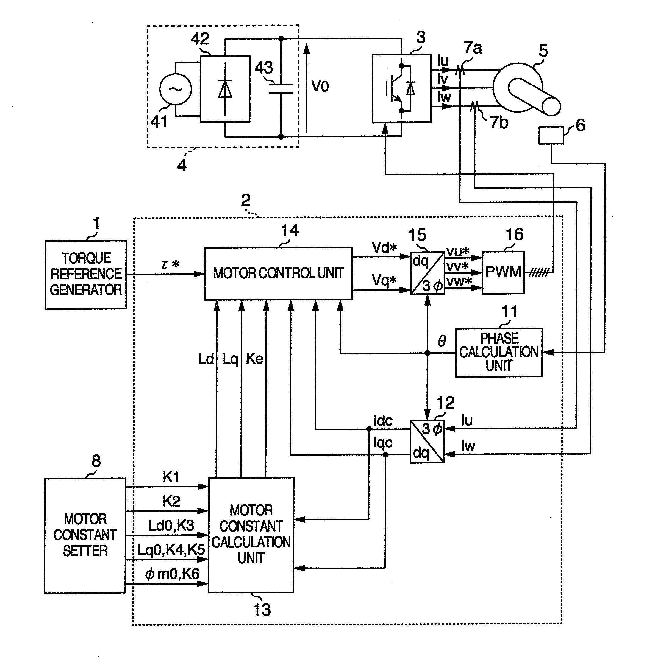
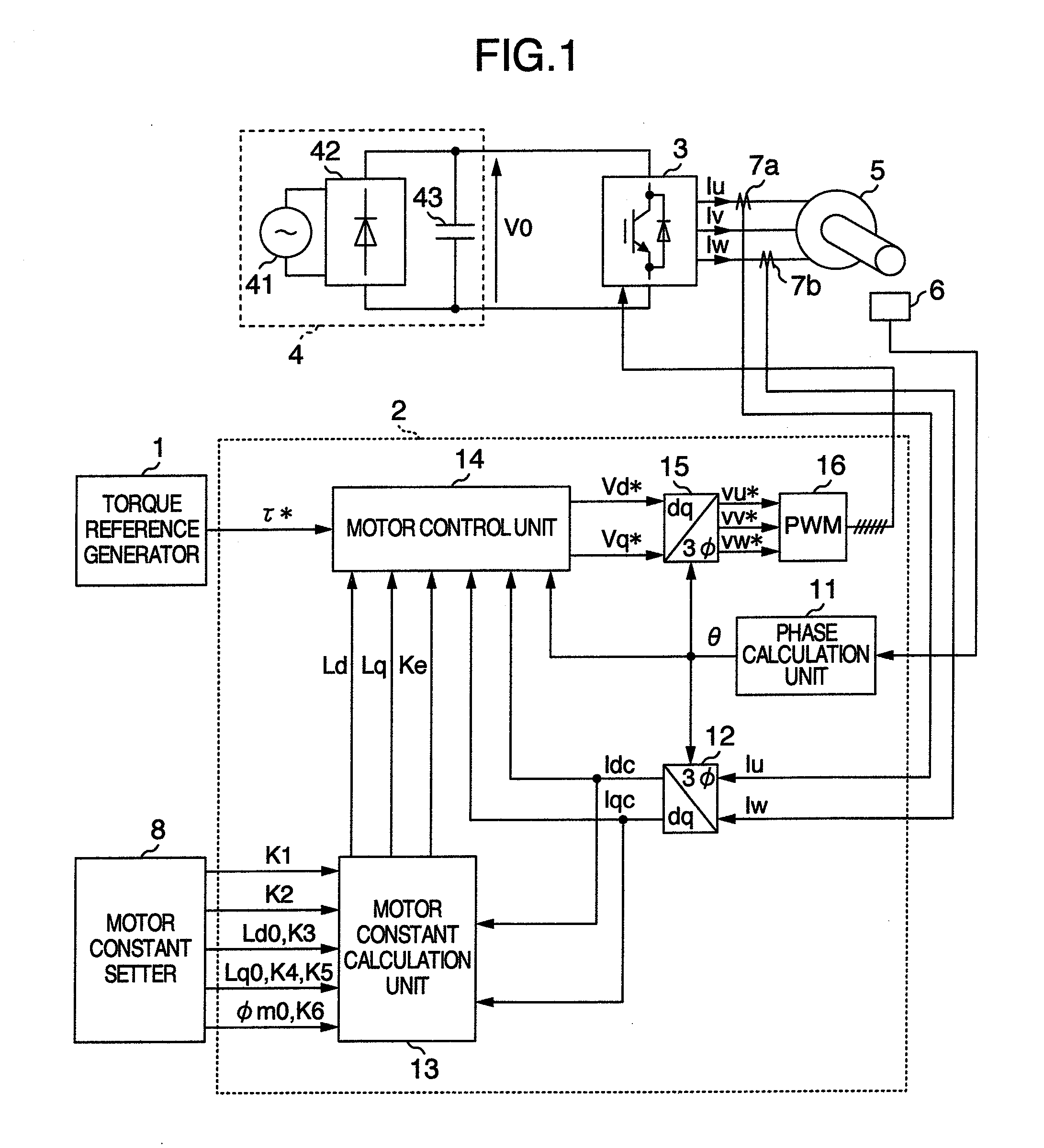
[0030]FIG. 1 is a block diagram showing a system configuration of embodiment 1 of a control apparatus of an AC motor according to the present invention. A control apparatus of the present embodiment 1 is configured by a torque reference generator 1 for giving torque reference τ* to a motor, a controller 2 for calculating AC applied voltage of a motor and for outputting it by converting to a pulse width modulated signal (hereafter abbreviated as a PWM signal), an inverter 3 driven by this PWM signal, a DC power source 4 for supplying power to the inverter 3, a permanent magnet type synchronous motor 5 (hereafter abbreviated as a PM motor) as a controlled object, a position detector 6 for detecting position of a rotor of the PM motor 5, an electric current detector 7a for detecting electric current Iu supplied to the PM motor by the inverter 3, an electric current detector 7b for detecting electric current Iw, and a motor constant setter 8 for setting constants K1, K2, K3, K4, K5, K6,...

embodiment 2

[0063]In embodiment 2, the motor control unit 14 is substituted with a motor control unit 14a shown in FIG. 8. Different points of FIG. 8 from FIG. 2 are absence of conversion coefficient 32, and calculation of a torque estimation value τc by being provided with a torque calculation unit 37.

[0064]The electric constants Ld, Lq and Ke of the PM motor, which are output by the motor constant calculation unit 13, and detected currents Idc and Iqc are input to the torque calculation unit 37, and the torque estimation value τC is calculated by the following function expression.

τc=Ke×Iqc+(Ld−Lq)×Idc×Iqc  (Equation 15)

[0065]By using electric constants Ld, Lq and Ke of the PM motor, which are output by the motor constant calculation unit 13, in torque estimation calculation, as described above, which is features of the present invention, highly precise torque control and high response can be attained, even when electric constants of a motor vary with increase in motor electric current caused ...

embodiment 3

[0066]In embodiment 1 and embodiment 2, explanations were given on configuration of the case having both a position sensor and an electric current sensor, however, configuration of the case having a position sensorless and an electric current sensor is also attainable. Explanation will be given with reference to FIG. 9.

[0067]Different points of FIG. 9 from FIG. 1 are as follows. Firstly, the torque reference generator 1 is substituted with a speed reference generator 1a, the motor control unit 14 is substituted with a motor control unit 14b, and still more the position detector 6 and the phase calculation unit 11 are eliminated, and phase angle θdc is supplied from the motor control unit 14b.

[0068]As for a setting method for the electric constants, a method explained in embodiment 1 is used.

[0069]Next, explanation will be given in detail on actuation of the motor control unit 14b with reference to FIG. 10.

[0070]Configuration of the motor control unit 14b shown in the present embodi...


PUM


Abstract

It is attained by being provided with a motor constant calculation unit for calculating electric constants of a motor, and by correcting setting values of electric constants defined on one of the axes of two orthogonal axes, by a functional expression using a state variable defined on the same axis, and by correcting them by a functional expression using a state variable defined on the other axis.

Description

BACKGROUND OF THE INVENTION[0001]The present invention relates to a control apparatus for an AC motor, in particular, the present invention relates to setting of electric constants of an AC motor.[0002]An AC motor, in particular, a permanent magnet synchronous motor has been extending the application ranges such as consumer electronics, industry, automobiles, by utilization of features of a compact size and high efficiency. In particular, in recent years, products having a motor drive system replaced from a square wave energization type to a sinusoidal wave energization type, and there has increased a controller essentially requiring input of electric constants setting values of a motor, such as resistance, inductance and back EMF (electromotive force) constant, in applications such as rotator position estimation by position sensorless control, or high precision torque control. Therefore, input without correct identification of electric constants of a motor influences on control per...

Claims


Application Information

Patent Timeline
Patent Type & Authority Applications(United States)
IPC IPC(8): H02P21/14H02P6/18H02P6/06H02P6/08H02P6/16H02P6/182H02P6/28H02P21/00H02P21/13H02P21/18H02P21/22H02P21/24H02P23/07H02P23/14H02P23/16H02P27/04H02P27/08
CPCH02P21/14
Inventor NAKATSUGAWA, JUNNOSUKEIWAJI, YOSHITAKATOBARI, KAZUAKISAKAMOTO, KIYOSHI
Owner HITACHI LTD
Why Eureka
Try Eureka