In-vehicle battery monitor

a battery monitor and in-vehicle technology, applied in the field of vehicles, can solve the problems of difficult to determine, difficult to monitor the condition of the storage battery used in such vehicles, and difficult to implement techniques

Inactive Publication Date: 2005-02-01
MIDTRONICS
View PDF382 Cites 176 Cited by
  • Summary
  • Abstract
  • Description
  • Claims
  • Application Information

AI Technical Summary

Problems solved by technology

It has typically been difficult to monitor the condition of the storage battery used in such vehicles.
This difficulty relates to all of the variables which are factors in determining the condition of the battery, as well as the electrical connections which are made to the battery during its use.
However, this technique is often quite difficult to implement because it is difficult to determine which particular characterization curve the battery may be following as well as precisely where on a particular characterization curve a battery may lie at a given moment.
This has made it difficult for a vehicle operator to accurately and in real time determine the condition of the vehicle's battery.
Further, a battery that is capable of providing sufficient power at one temperature, may fail the next morning if the temperature drops over night.
Further, such techniques may not account for situations in which the battery is fully charged and any additional current going into the battery is simply lost as heat or a situation in which the battery charge decreases during periods on non-use.

Method used


Image

  • In-vehicle battery monitor
  • In-vehicle battery monitor
  • In-vehicle battery monitor

Examples


Embodiment Construction

The present invention offers an apparatus and method for monitoring the condition of the battery and optionally controlling charging of the battery. Such a method and apparatus can be part of a general energy management system for a vehicle.

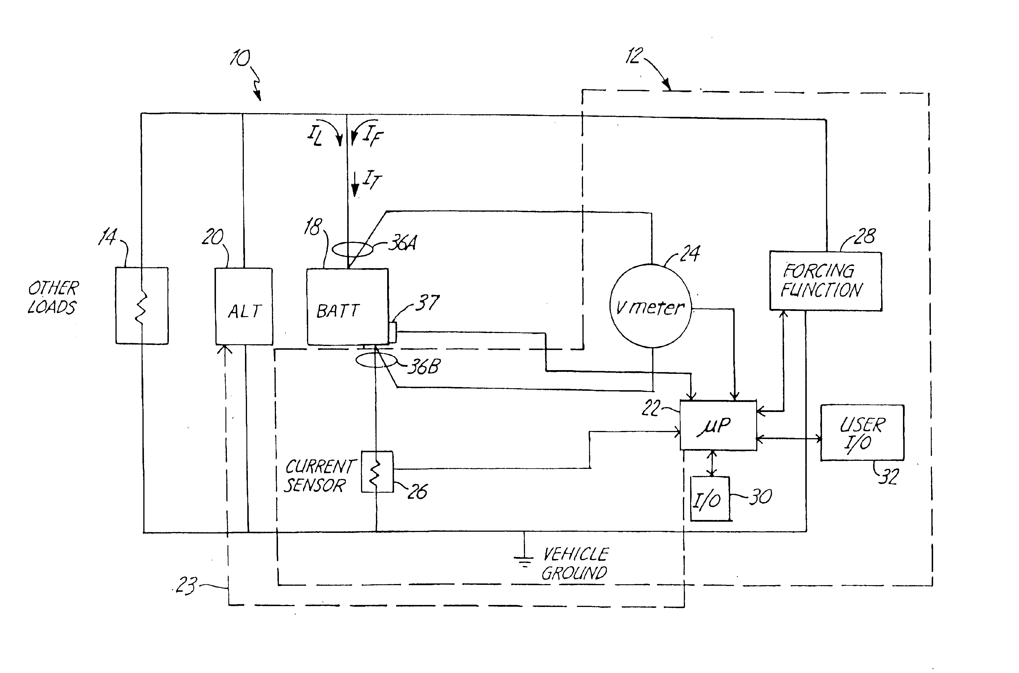
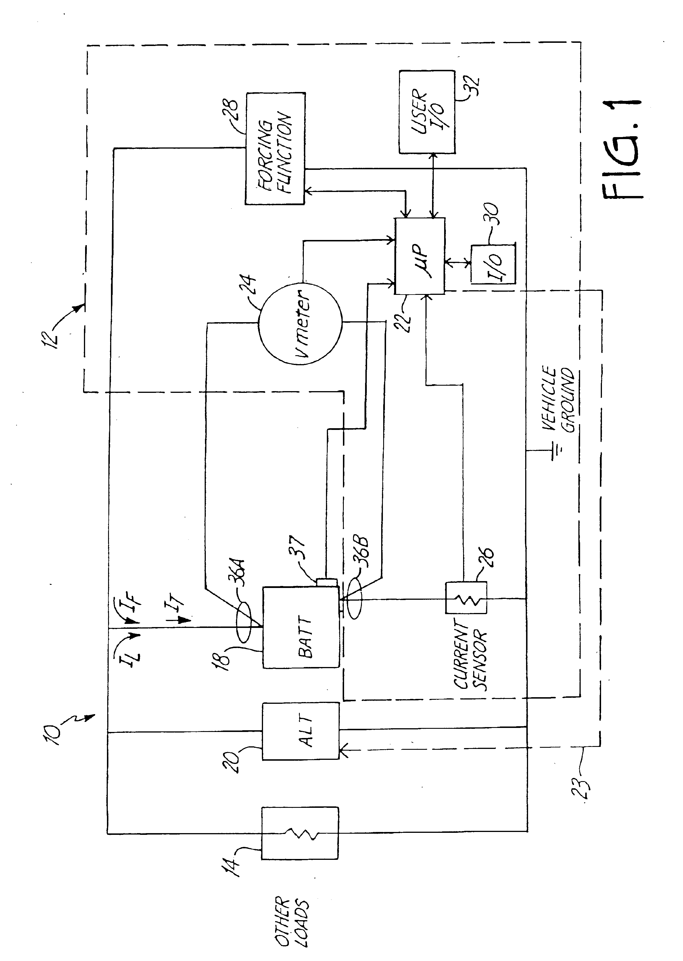
FIG. 1 is a simplified block diagram showing an automotive vehicle 10 which includes a battery monitor 12 in accordance with one embodiment of the present invention. Vehicle 10 includes vehicle loads 14 which are shown schematically as an electrical resistance. A battery 18 is coupled to the vehicle load 14 and to an alternator 20. Alternator 20 couples to an engine of the vehicle 10 and is used to charge battery 18 and provide power to loads 14 during operation.

In general, automotive vehicles include electrical systems which can be powered when the engine of the vehicle is operating by a generator, or alternator. However, when the engine is not running, a battery in the vehicle is typically used to power the system. Thus, the standard generator ...


PUM

PropertyMeasurementUnit
open-circuit voltageaaaaaaaaaa
SOLaaaaaaaaaa
temperatureaaaaaaaaaa

Abstract

An apparatus and a method of monitoring a battery in an automotive vehicle are provided. An output is provided which can be a relative output as a function of minimum and maximum parameters of the battery.

Description

BACKGROUND OF THE INVENTIONThe present invention relates to vehicles. More specifically, the present invention relates to battery monitors used to monitor batteries used in vehicles. Vehicles, both automotive and electric, typically include a storage battery. For example, automotive vehicles powered by combustion engines typically include a battery. The battery is used to power the electrical system when the engine is not running. Additionally, the engine is used to charge the battery. The engine is also used to power electrical components of the vehicle when the engine is running.It has typically been difficult to monitor the condition of the storage battery used in such vehicles. This difficulty relates to all of the variables which are factors in determining the condition of the battery, as well as the electrical connections which are made to the battery during its use. Attempts have been made to characterize the operation of a battery and use “characterization curves” to determi...

Claims


Application Information

Patent Timeline
Patent Type & Authority Patents(United States)
IPC IPC(8): G01R31/36H02J7/00H02J7/16G01R31/00B60L3/00H01M10/48H02J7/14
CPCG01R31/36G01R31/3624G01R31/3627G01R31/3648H02J7/0004H02J7/0008H02J7/008H02J7/163G01R31/007Y02T10/7005G01R31/3693G01R31/3675G01R31/385G01R31/3647G01R31/3842G01R31/374H02J7/00041H02J7/00036H02J7/00047Y02T10/70H02J7/00714H02J7/007182
Inventor BERTNESS, KEVIN I.
Owner MIDTRONICS
Why Eureka
Try Eureka