Anti-collision safety system for vehicle

a safety system and vehicle technology, applied in the direction of vehicle components, signalling/lighting devices, optical signalling, etc., can solve the problems of slow response time of the system, proposed devices are not continuously operable, and conventional stop lamps do not relay information to following vehicles. , to achieve the effect of fast illumination build tim

Inactive Publication Date: 2005-02-01
DONNELLY CORP
View PDF27 Cites 173 Cited by
  • Summary
  • Abstract
  • Description
  • Claims
  • Application Information

AI Technical Summary

Benefits of technology

The present invention is intended to provide an anti-collision safety light control which adjusts or modulates an output of an exterior light of a vehicle in response to at least one, and preferably multiple, inputs associated with one or more conditions of the vehicle. Preferably, the anti-collision safety light system is a solid state device which modulates or otherwise adjusts an output of a stop lamp in response to a deceleration of the vehicl

Problems solved by technology

However, conventional stop lamps do not relay information to following vehicles pertaining to the rate of deceleration or degree of braking of the subject vehicle.
Accordingly, the proposed devices are not continuously operable, since they are only energized when power to the brake lights is also applied.
This results in a slower response time of the system, since the system must power-up and determine if the lamp should be flashed after the brake pedal has been depressed.
Not only does this result in a delay before the system will react to modulate the stop lamp or separate light, but this further results in a shorter life cycle of the system, since the system is turned on and off every time the brake pedal is depressed.
Another issue with such systems is that they are costly and difficult to implement on existing vehicles, since many of these systems include mechanical devices which are separately installed and/or must be properly oriented within the vehicle.
However, such a device fails to account for the various configurations of light sockets on different vehicles, which make it difficult to properly orient the device in many applications.
While most of the proposed devices have not achieved commercial success, some cars today are equipped with brake light systems which flash the stop lamp automatically any time the brake pedal is depressed.
However, the lamps associated with these devices may flash during ordinary braking as well as panic braking or other sudden stopping

Method used


Image

  • Anti-collision safety system for vehicle
  • Anti-collision safety system for vehicle
  • Anti-collision safety system for vehicle

Examples


Embodiment Construction

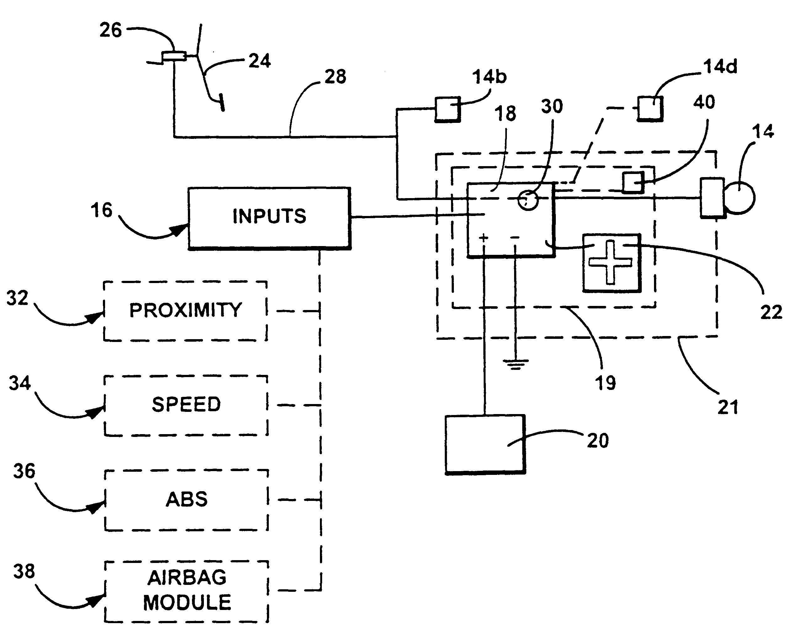
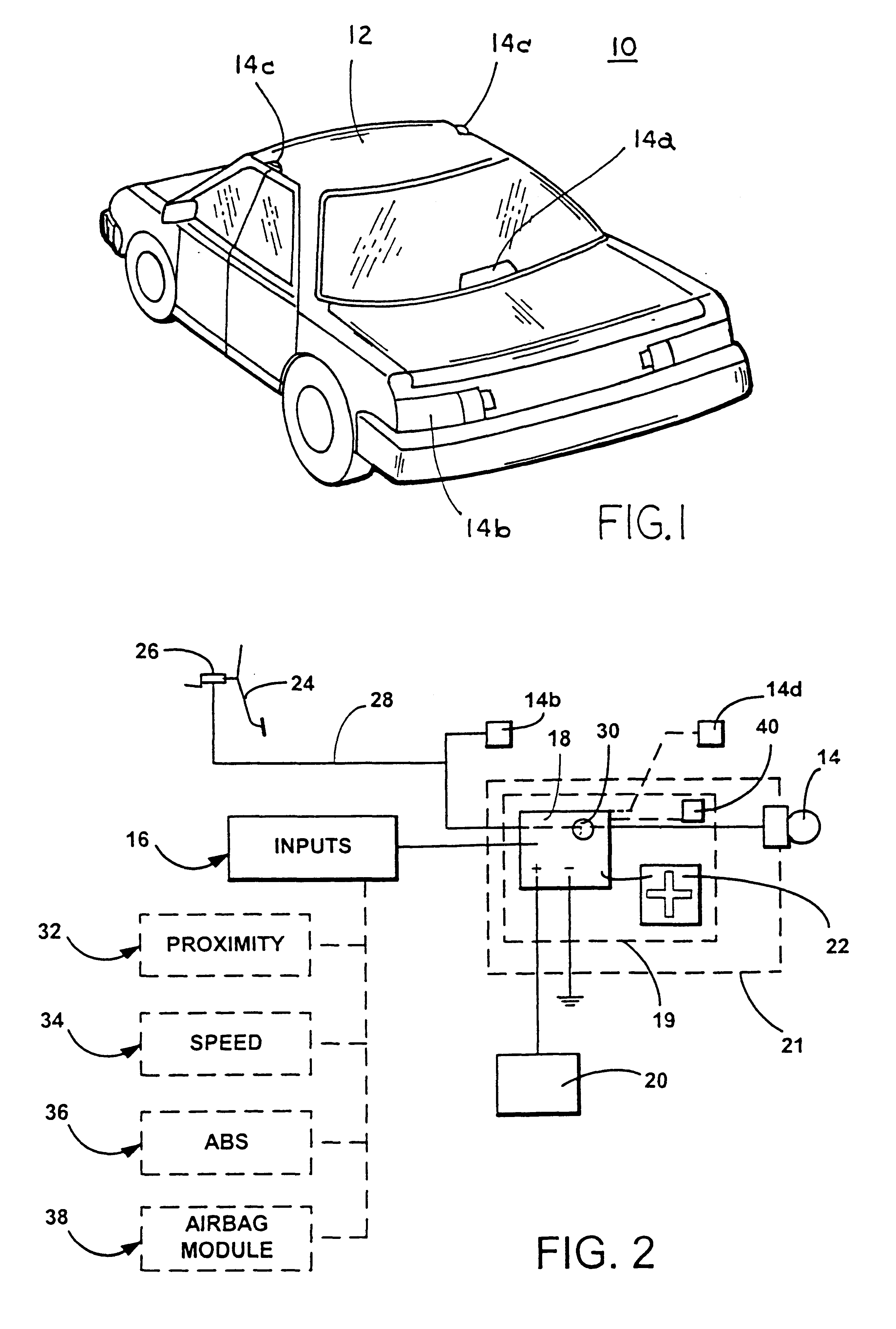
Referring now specifically to the drawings and the illustrative embodiments depicted therein, a vehicular anti-collision safety light system 10 is positioned on a vehicle 12, which may be an automobile, a light truck, a van, a large truck or semi-trailer, a sport utility vehicle or the like (FIG. 1). Safety light system 10 is interconnected with an indicator 14 and actuates, adjusts or modulates an output of indicator 14 in response to one or more electronic inputs 16 (FIG. 2). Preferably, indicator 14 is a center high mounted stop lamp (CHMSL) 14a of vehicle 12, but may be another exteriorly directed light or lights on vehicle 12, such as taillights 14b, headlamps, turn signal indicators or the like or a separately installed signaling device. As shown in FIG. 2, safety light system 10 includes a microprocessor or control 18 which is preferably interconnected with an accelerometer 22. Accelerometer 22 is operable to detect and measure G forces acting on vehicle 12 and to provide a s...


PUM


Abstract

An anti-collision safety system for a vehicle includes a microprocessor which receives one or more inputs and controls an output of at least one indicator or signaling device in response to the inputs. The microprocessor may be continuously powered or energized when the vehicle is in use, such that the indicator may be modulated in situations when the brake pedal of the vehicle is not applied. Preferably, a proximity sensing device may be provided to detect objects exteriorly of the vehicle. Preferably, an accelerometer may also be included to provide a deceleration signal to the microprocessor. The microprocessor may modulate the indicator independent of actuation of the brake pedal by a driver of the vehicle.

Description

BACKGROUND OF THE INVENTIONThis invention relates generally to safety lights for vehicles and, more particularly, to a safety light control to warn a driver of another vehicle of a hazardous condition associated with the subject vehicle.Brake lights vehicles are provided on vehicles to signal drivers of other vehicles that the brake system of the subject vehicle has been actuated. In order to reduce rear end collisions, center high mounted stop lamps (CHMSL) have been added to most vehicles to further enhance visibility of the brake lamps when they are activated. However, conventional stop lamps do not relay information to following vehicles pertaining to the rate of deceleration or degree of braking of the subject vehicle.Some proposed devices flash the stop lamp or illuminate and / or flash a separate light on the vehicle when the vehicle is braking, in order to further alert other drivers. These systems are triggered by actuation of the brake system of the vehicle, such that the fl...

Claims


Application Information

Patent Timeline
IPC IPC(8): B60Q1/50B60Q1/44B60Q1/52B60Q1/30
CPCB60Q1/302B60Q1/52B60Q1/448B60Q1/535
Inventor BLOOMFIELD, JOHNLYNAM, NIALL R.
Owner DONNELLY CORP
Why Eureka
Try Eureka