Check patentability & draft patents in minutes with Patsnap Eureka AI!

Ladder stabilizer

a technology of ladders and stabilizers, applied in the field of ladder stabilizers, can solve the problems of ladder related injuries costing over 11 billion dollars annually, causing accidents to wait to happen, and causing medical, legal, liability and pain and suffering expenses

Inactive Publication Date: 2005-02-08
WALKER JAMES SCOTT
View PDF12 Cites 32 Cited by
  • Summary
  • Abstract
  • Description
  • Claims
  • Application Information

AI Technical Summary

Benefits of technology

The primary objective of the current invention is to provide a ladder stabilizer that is extendable to prevent lateral movement of a ladder against a flat surface. A second objective of the invention is to allow for the placement of an extension ladder on a non-flat surface, including a roof, with extendable support for any pitch surface, from horizontal to vertical. A third objective is to provide the ladder stabilizer for use on the bottom of an extension ladder for stable contact with the ground in a variety of configurations. A fourth objective of the ladder stabilizer is to provide the extension arms to be adjusted to wrap and secure a round pole to prevent lateral movement while working on a utility or sign pole.

Problems solved by technology

Estimated cost of ladder related injuries is over 11 billion dollars annually, including loss of work, medical, legal, liability and pain and suffering expenses.
However, even following these guidelines can still leave accidents waiting to happen, since extension ladders may still teeter and move laterally when resting against walls roofs or other surfaces.

Method used


Image

  • Ladder stabilizer
  • Ladder stabilizer
  • Ladder stabilizer

Examples


Embodiment Construction

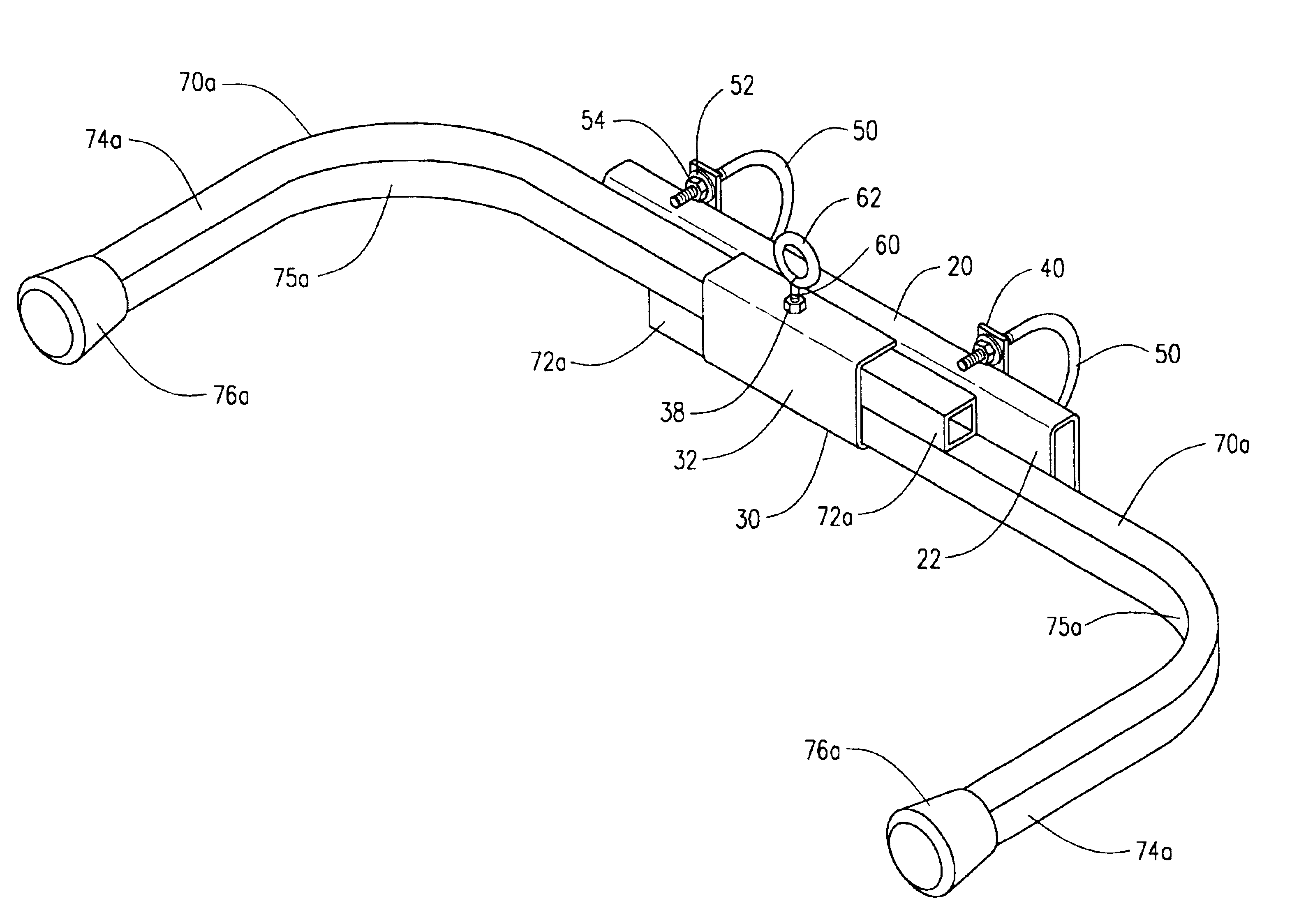
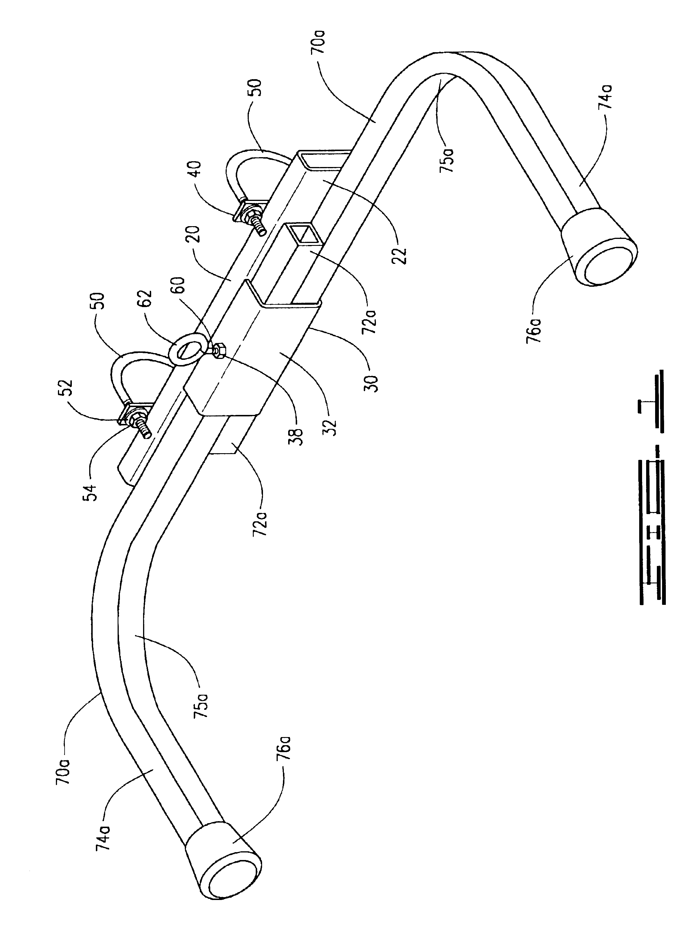
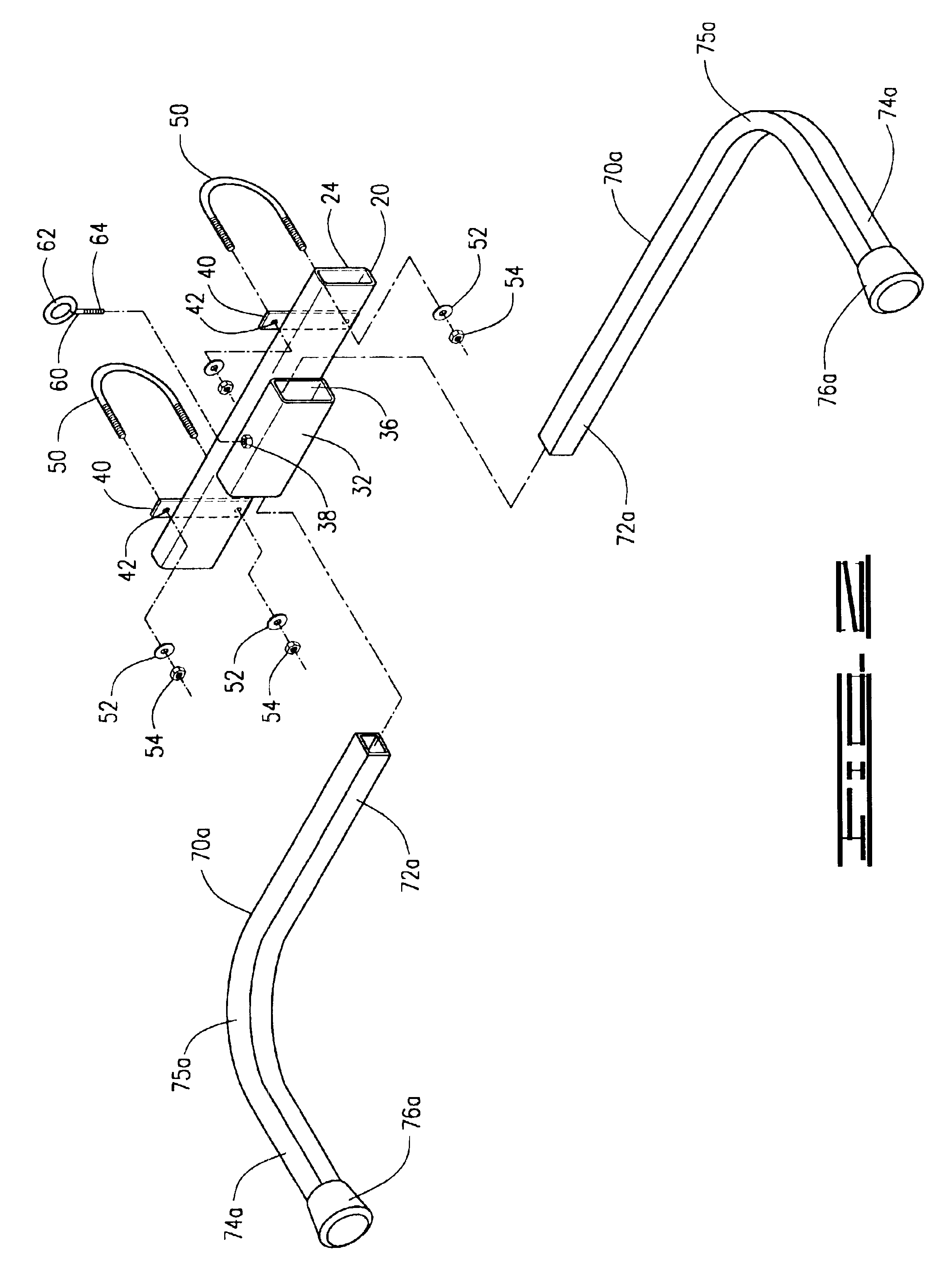
A ladder stabilizer, shown in FIGS. 1-5 of the drawings, adapted to attach to a rung 102 of an extension ladder 100, the ladder stabilizer comprising a main support bracket 20 having a front surface 22 and a rear surface 24, a sliding channel 30 having a front surface 32, a rear surface 34, an inner transverse sliding cavity 36, and an upper threaded bore 38, the rear surface 34 of the sliding channel 30 attached to the front surface 22 of the main support bracket 20, at least two U-bolt brackets 40 having a pair of vertically oriented holes 42 per each U-bolt bracket 40 attached to the rear surface 24 of the main support bracket 20, the pair of holes 42 in each U-bolt bracket 30 receiving a U-bolt 50 secured by washers 52 and nuts 54, the U-bolts 50 attaching each U-bolt bracket 40 to a common extension ladder rung 102, and two bent angled service arms 70a, 70b, slidingly engaged within the sliding channel 30, secured within the sliding cavity 36 at a chosen position by an external...


PUM


Abstract

A ladder stabilizer adapted to attach to an upper end or lower end of an extension ladder includes a mounting plate connecting to a rung of the extension ladder by secure U-bolts, the mounting plate attached to a slide bar mounting bracket having a transverse channel with a tightening screw providing a force within the channel to lock and hold a pair of extendable service arms within the transverse channel to provide additional wide and secure lateral stabilization of the extension ladder either at the top of the extension ladder, where the extension ladder rests against a wall or roof, or at the bottom of the extension ladder where the extension ladder meets the ground.

Description

I. BACKGROUND OF THE INVENTION1. Field of InventionA ladder stabilizer adapted to attach to an upper end or lower end of an extension ladder includes a mounting plate connecting to a rung of the extension ladder by secure U-bolts, the mounting plate attached to a slide bar mounting bracket having a transverse channel with a tightening screw providing a force within the channel to lock and hold a pair of extendable service arms within the transverse channel to provide additional wide and secure lateral stabilization of the extension ladder either at the top of the extension ladder, where the extension ladder rests against a wall or roof, or at the bottom of the extension ladder where the extension ladder meets the ground.2. Description of Prior ArtThe following United States patents were discovered and are disclosed within this application for utility patent. All relate to extension ladder stabilizers or support devices.In two U.S. Des. Pat. No. D406,652 to Marchland and U.S. Pat. No...

Claims


Application Information

Patent Timeline
IPC IPC(8): E06C7/48E06C7/42E06C7/00
CPCE06C7/48E06C7/42
Inventor WALKER, JAMES SCOTT
Owner WALKER JAMES SCOTT
Features
  • R&D
  • Intellectual Property
  • Life Sciences
  • Materials
  • Tech Scout
  • Unparalleled Data Quality
  • Higher Quality Content
  • 60% Fewer Hallucinations
Learn More