Ankle-joint endoprosthesis

an endoprosthesis and ankle joint technology, applied in the field of ankle joint endoprosthesis, to achieve the effect of avoiding imbalan

Inactive Publication Date: 2005-02-08
LINK AMERICA INC
View PDF8 Cites 51 Cited by
  • Summary
  • Abstract
  • Description
  • Claims
  • Application Information

AI Technical Summary

Problems solved by technology

However, it has been found that, after surgery, the collateral and medial ligaments of the ankle often have different tensioning, which can cause difficulties.

Method used


Image

  • Ankle-joint endoprosthesis
  • Ankle-joint endoprosthesis

Examples


Embodiment Construction

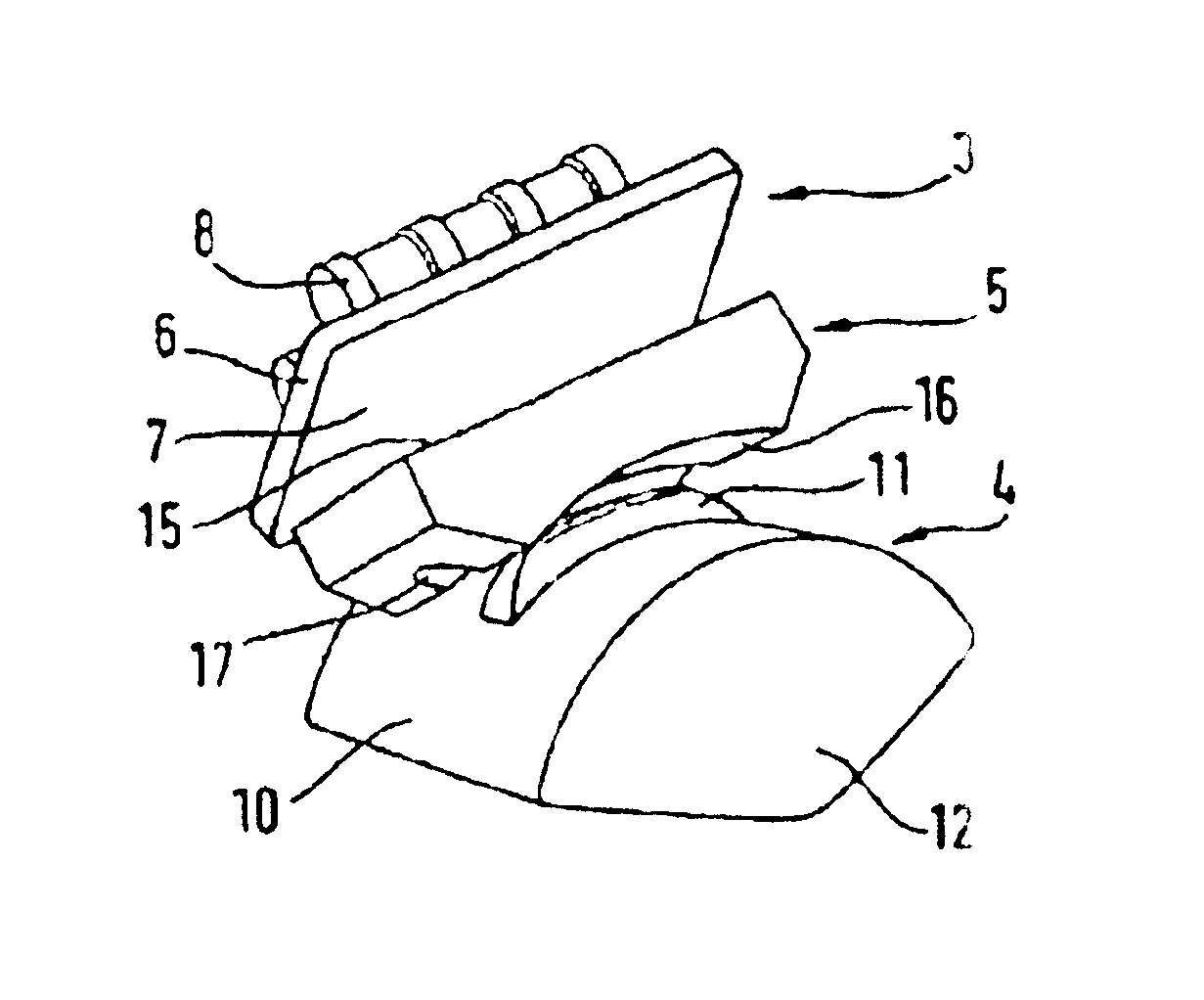
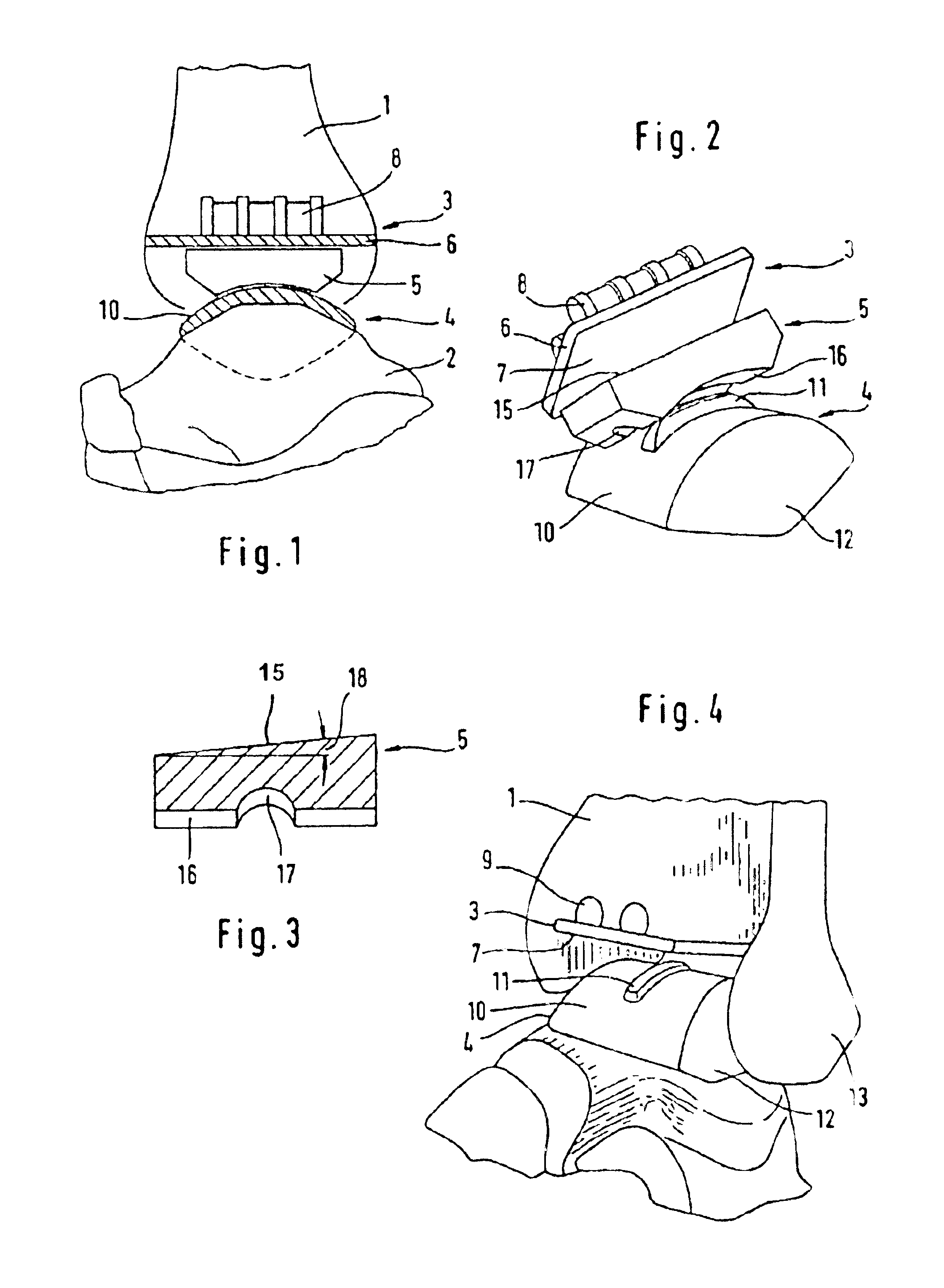
The prosthesis consisting of the tibial component 3, the anklebone component 4 and the middle part 5 is to be arranged between the tibia 1 and the anklebone 2. The tibial component 3 has a plate-like part 6 whose underside 7 forms a flat slide surface. Projections 8 serve to secure it in corresponding resected cavities 9 in the tibia 1.

The anklebone component 4 forms a convexly curved slide surface 10 which can be of cylindrical or conical design. It has a rib 11 which lies in the direction of the relative movement of the middle part upon the flexion and extension movement. The anklebone component also has lateral facets 12 for interacting with corresponding slide surfaces of the tibia 1 and of the fibula 13.

The middle part 5 has a flat top 15 matching the slide surface 7, and a lower slide surface 16 which is designed congruent with the slide surface 10 of the anklebone component 4. It has a groove 17 for receiving the rib 11. In this way, the middle part 5 is guided laterally in r...


PUM


Abstract

An endoprosthesis for replacement of the ankle joint includes a component which is to be connected to the anklebone and which forms an upper slide surface a component which is to be connected to the tibia and which forms a lower slide surface, and a middle part. The middle part forms two slide surfaces which interact with slide surfaces on the tibial component and the anklebone component. In frontal section, the middle part is wedge-shaped with a wedge angle of between 1° and 12°.

Description

FIELD AND BACKGROUND OF THE INVENTIONFor replacement of the ankle joint, an endoprosthesis is known which consists of a component to be connected to the anklebone, a component to be connected to the tibia, and a middle part (DE-U-8812806; brochure entitled “LINK S.T.A.R. Totale Sprunggelenkprothese [H. Kofoed] by the company Waldemar Link (flexion and extension in the sagittal plane. The tibial component and the middle part form interacting slide surfaces which permit a rotation about the vertical axis. They can be made flat in order to GmbH & Co.), Hamburg). The anklebone component and the middle part interact via slide surfaces which permit compensating movements in the AP (anterior-posterior) direction and LM (lateral-medial) direction. Stabilization is effected by means of the natural ligament apparatus.In the known prosthesis, the upper and lower slide surfaces of the middle part are oriented parallel to one another in the frontal plane. This is logical insofar as the aim is to...

Claims


Application Information

Patent Timeline
Patent Type & Authority Patents(United States)
IPC IPC(8): A61F2/42A61F2/00A61F2/30
CPCA61F2/4202A61F2310/00179A61F2002/30158A61F2002/30233A61F2002/30393A61F2002/30395A61F2002/30398A61F2002/30604A61F2002/30616A61F2002/3082A61F2002/30878A61F2002/30881A61F2002/30892A61F2002/30934A61F2002/4205A61F2002/4207A61F2220/0025A61F2230/0019A61F2230/0026A61F2230/0069A61F2310/00011A61F2002/30153A61F2/42
Inventor KELLER, ARNOLDKOFOED, HAKON
Owner LINK AMERICA INC
Why Eureka
Try Eureka