System and method for correcting aberration of lenses through which images are projected

a technology of aberration correction and scanner lens, which is applied in the field of aberration correction, can solve the problems of affecting the image quality of the subject image projected through the scanner lens, the difficulty of designing a lens with minimal aberration, and the decline in the image quality of the subject image on the photographic film, so as to facilitate the determination of the information on the aberration of the second lens

Inactive Publication Date: 2005-02-08
FUJIFILM CORP
View PDF8 Cites 61 Cited by
  • Summary
  • Abstract
  • Description
  • Claims
  • Application Information

AI Technical Summary

Benefits of technology

The present invention has been devised to overcome the above-described problems, and its object is to provide an aberration correcting method which makes it possible to obtain photographic prints of excellent image quality in a case where a subject is imaged by a camera to record the subject image on a photographic film, image data representing the subject image is obtained by reading the photographic film by a scanner, and a photographic print representing the subject image is prepared on the basis of the obtained image data.
Thus it is possible to efficiently correct the declines in the image quality of the subject image represented by the image data obtained by reading with the image reading means, which declines are due to the aberrations of the first and second lenses.
In addition, even in a case where an imaging means having an inexpensive lens and an image reading means (scanner or the like) having an inexpensive lens are used, excellent image quality can be obtained.
In this way, aberration correction of the aberrations of the first and second lenses is carried out simultaneously only in the case in which the aberration amount of the first lens is greater than or equal to the predetermined aberration amount. Thus, aberration correction can be carried out appropriately in accordance with the magnitude of the aberration of the first lens.
For instance, if the image data obtained by reading and the image data of the predetermined image for inspection are developed in the same two-dimensional coordinate system through image processing, the distortion of the image of the image for inspection due to the aberration of the second lens can be detected from the offset, distortion, and the like of the images developed in the two-dimensional coordinate system. Then, information on the aberration of the second lens is determined from the detected distortion of the image of the image for inspection. Thus, it is possible to easily determine the information on the aberration of the second lens.

Problems solved by technology

Since lenses generally have aberrations, there is a possibility that the subject image projected through the aforementioned camera lens and the subject image on the photographic film projected through the scanner lens suffer a decline in their image quality due to the aberrations of the lenses.
With respect to the scanner lens, in particular, since the magnification of projection onto a CCD is close to a 100% magnification, it is difficult to design a lens with minimized aberrations.
For this reason, there is concern of a decline in the image quality of the subject image on the photographic film, which subject image is projected through the scanner lens.
Moreover, with the above-described technique, there is a possibility that the image quality of photographic prints prepared declines substantially due to both the aberration of the camera lens and the aberration of the scanner lens.

Method used


Image

  • System and method for correcting aberration of lenses through which images are projected
  • System and method for correcting aberration of lenses through which images are projected
  • System and method for correcting aberration of lenses through which images are projected

Examples


Embodiment Construction

Referring now to the accompanying drawings, a description will be given of an embodiment of the present invention.

Schematic Configuration of Digital Lab System

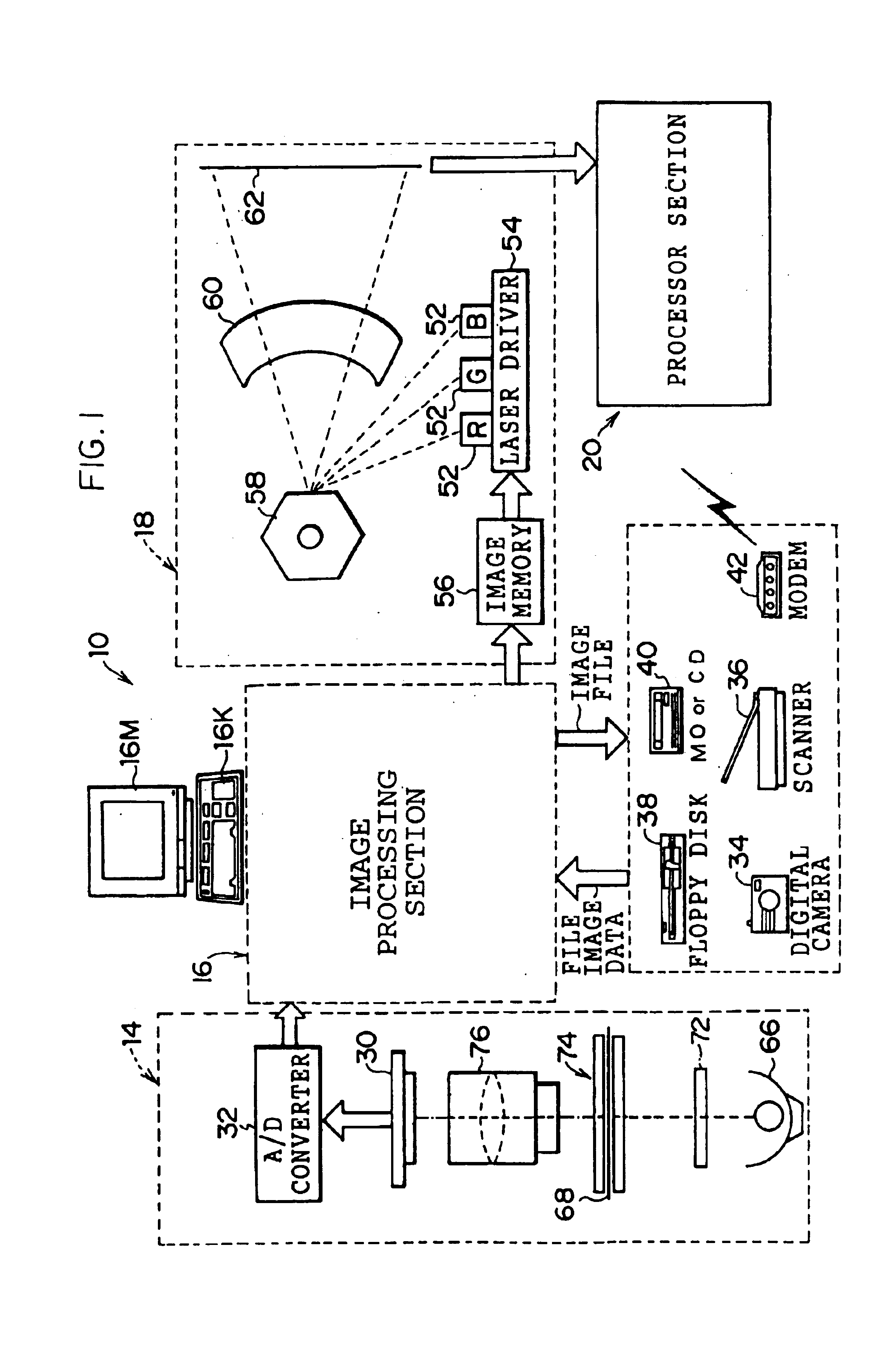
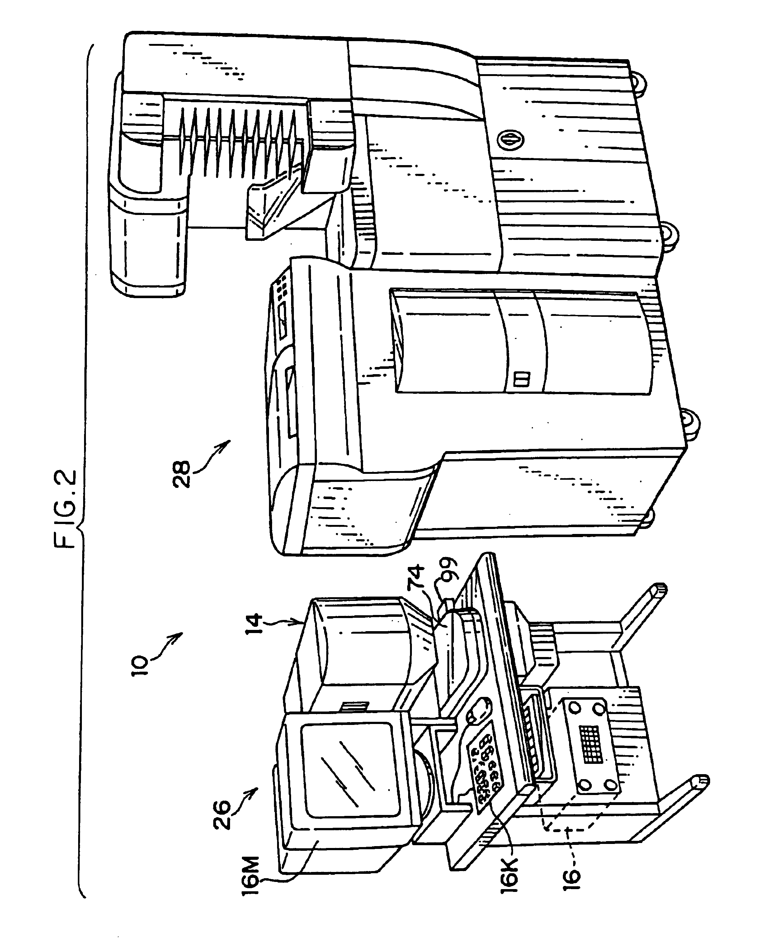
FIGS. 1 and 2 show a schematic configuration of a digital lab system 10 in accordance with this embodiment.

As shown in FIG. 1 this digital lab system 10 is comprised of a line CCD scanner 14, an image processing section 16, a laser printer section 18, and a processor section 20. The line CCD scanner 14 and the image processing section 16 are integrated as an input section 26 shown in FIG. 2, while the laser printer section 18 and the processor section 20 are integrated as an output section 28 shown in FIG. 2.

The line CCD scanner 14 is for reading frame images recorded on a photographic film such as a negative film or a reversal film, and its objects to be read can be frame images on photographic films, e.g., a 135-size photographic film, a 110-size photographic film, a photographic film with a transparent magnetic layer formed...


PUM


Abstract

In a case where aberrations of a camera lens are large, and imaging-center coordinates and reading-center coordinates coincide with each other or are located in proximity to each other within an allowable range, and trimming was not effected or center trimming was not effected, correction parameters for correcting the aberrations of the camera lens and correction parameters for correcting the aberrations of a scanner lens are integrated, and the deterioration of image quality caused by the aberrations of the camera lens and the deterioration of image quality caused by the aberrations of the scanner lens are corrected simultaneously by using the integrated parameters.

Description

BACKGROUND OF THE INVENTION1. Field of the InventionThe present invention relates to an aberration correcting method, and more particularly to an aberration correcting method wherein after an image of a subject projected through a first lens is imaged, aberration correction is performed with respect to image data obtained by projecting through a second lens the subject image recorded on a photographic photosensitive material by the imaging, and by reading the subject image.2. Description of the Related ArtConventionally, a technique is known in which a subject is photographed by a camera, a subject image is recorded on a photographic photosensitive material such as a photographic film (such a photographic photosensitive material will be hereafter referred to as photographic film), image data representing the subject image is obtained by reading the photographic film by a scanner, and a photographic print representing the subject image is prepared on the basis of the image data obtai...

Claims


Application Information

Patent Timeline
Patent Type & Authority Patents(United States)
IPC IPC(8): H04N5/225H04N5/228H04N1/46H04N5/217G02B15/14H04N1/401H04N5/372
CPCH04N1/401
Inventor MATAMA, TORU
Owner FUJIFILM CORP
Why Eureka
Try Eureka