Check patentability & draft patents in minutes with Patsnap Eureka AI!

Implantable cardiac stimulator with synchronization of the ventricular contractions

a technology of ventricular contraction and stimulator, which is applied in the direction of heart stimulators, electrotherapy, therapy, etc., can solve the problems that synchronized pacing does not necessarily provide the best possible synchronization of the actual contraction of the ventricles, and achieve the effects of improving the synchronization of mechanical contraction, and improving the synchronization of the ventricles

Inactive Publication Date: 2005-02-08
ST JUDE MEDICAL
View PDF4 Cites 11 Cited by
  • Summary
  • Abstract
  • Description
  • Claims
  • Application Information

AI Technical Summary

Benefits of technology

The purpose of pacing the left and right ventricles with separate leads is to improve the synchronization of the mechanical contraction of the two ventricles. The synchronization of the ventricles is very important for patients with severe congestive heart failure. These patients are often waiting for a heart transplant and optimal hemodynamic conditions during the time before the transplant is important for the outcome. A problem in this context is that synchronous pacing will not necessarily provide the best possible synchronization of the actual contraction of the ventricles. The present invention is based on the recognition that the synchronization of the ventricles may be improved compared to known devices if the cardiac stimulating device adjusts the timing of the stimulating pulses in order to optimize the synchronization in the contraction of the ventricles it is thus an object of the present invention to provide an implantable cardiac stimulating device by wherein the synchronization of the ventricles is improved.
According to a further embodiment of the invention, the control circuit compares the R-wave in the evoked response to the stimulation of the first ventricle with the R-wave in the evoked response to stimulation of the second ventricle. The R-wave is also called the QRS-complex. The R-wave is more closely related to the ventricular contraction than the delivered stimulating pulse. By making the R-waves in the left and right ventricles occur substantially simultaneously, a good synchronization of the ventricles is obtained.
In another embodiment of the invention, the 5 control circuit makes the comparison by measuring an integral of the difference between the R-wave in the evoked response to the stimulation of the first ventricle and the R-wave in the evoked response to stimulation of the second ventricle, and the time interval is set such that this integral is minimized. Since the R-wave in the evoked response to stimulation of the left ventricle may have a slightly different shape than the R-wave in the evoked response to stimulation of the right ventricle, by minimizing the aforementioned integral a substantially simultaneous contraction of the left and right ventricles is obtained.
According to another embodiment of the invention, the control circuit makes the comparison by measuring an integral of the difference between the T-wave in the evoked response to the stimulation of the first ventricle and the T-wave in the evoked response to stimulation of the second ventricle, and the time interval is set such that this integral is minimized. In the same manner as described above in connection with the R-wave, it is possible to make the contraction of the ventricles occur substantially simultaneously by minimizing the corresponding integral for the T-waves.
Furthermore, in a similar manner as to that described above in connection with the R-wave, it is possible to detect a slope or peak of the T-wave in the evoked response to stimulation of the ventricles. Also, in a manner similar to that described above it is advantageous to set the time interval by varying the time interval and by comparing the corresponding evoked response parameters.
The present invention is based on the recognition that the time gap between a stimulating pulse and the associated evoked response parameter can be monitored in order to detect heart problems, such as dissynchronization. Normally, when the pacing rate increases, the time gap between a stimulating pulse and the associated evoked response parameter becomes shorter. However, at a certain pacing rate, this time gap may stop decreasing although the pacing rate increases. The present invention is based on a recognition that such a situation is an indication of heart problems, such as a dissynchronization between the ventricles. According to this embodiment of the invention, an implantable cardiac stimulating device is provided which exposes the patient wearing the device to less risk, since the maximum pacing rate is lowered if the time gap does not decrease with increasing pacing rate.

Problems solved by technology

A problem in this context is that synchronous pacing will not necessarily provide the best possible synchronization of the actual contraction of the ventricles.

Method used


Image

  • Implantable cardiac stimulator with synchronization of the ventricular contractions
  • Implantable cardiac stimulator with synchronization of the ventricular contractions
  • Implantable cardiac stimulator with synchronization of the ventricular contractions

Examples


Embodiment Construction

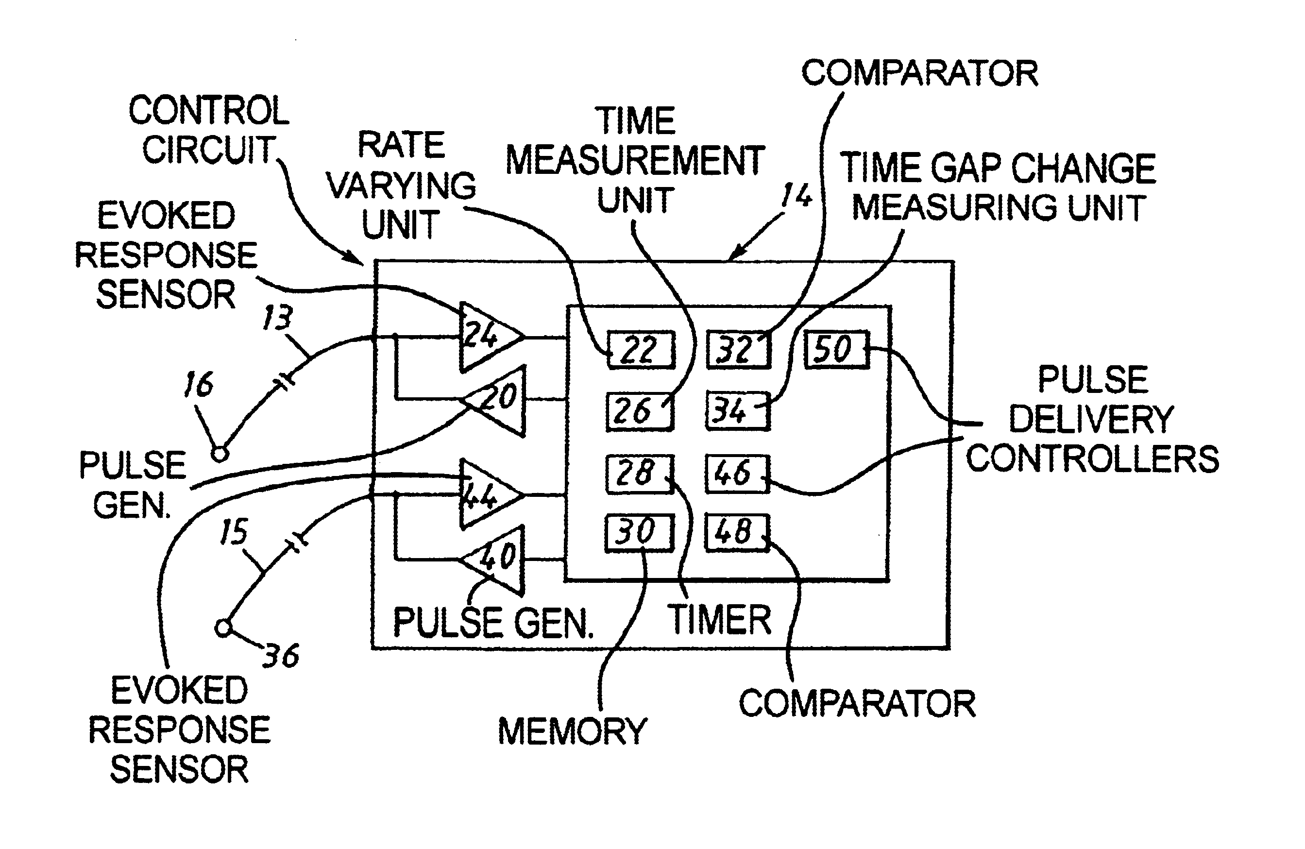
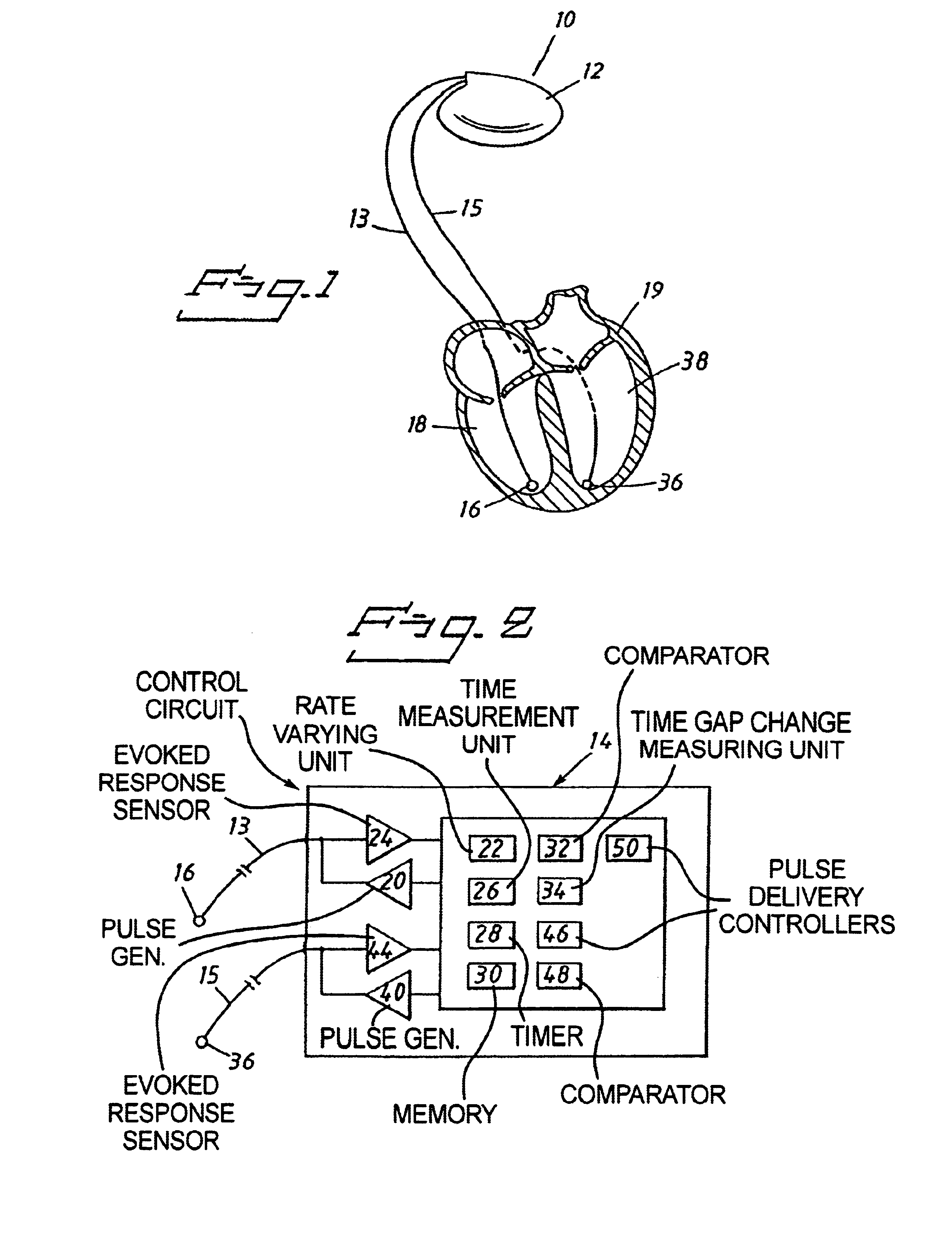
FIG. 1 shows an implantable cardiac stimulating device 10, here in after also called a pacemaker, according to the invention. The pacemaker 10 has a housing 12. A control circuit 14 (see FIG. 2) is enclosed in the housing 12. The control circuit 14, and thereby the pacemaker 10, is adapted to be connected to a first electrode 16. FIG. 1 shows such an electrode 16 which is connected to the pacemaker 10 via a lead 13. The first electrode 16 is adapted to be positioned to stimulate a first ventricle 18 of the heart 19. The first ventricle 18 is in this case the right ventricle. According to the invention, the pacemaker 10 is also adapted to be connected to a second electrode 36. FIG. 1 shows such a second electrode 36 connected to the housing 12 via a lead 15. The second electrode 36 is positioned to stimulate a second ventricle 38 of the heart 19. The second ventricle 38 is in this case the left ventricle. The electrodes 16, 36 may include more than one electrical conductor in order t...


PUM


Abstract

An implantable cardiac stimulating device has a control circuit connected to first and second electrodes respectively for stimulating first and second ventricles of a heart. Evoked response sensors respectively sense evoked response parameters to stimulation of the two ventricles. Delivery of stimulating pulses via the respective electrodes to the respective ventricles in the same cycle of the heart is controlled so that there is a time interval between the pulses respectively delivered to the two ventricles. The control circuit controls delivery of the stimulating pulses so that the respective evoked response parameters of the two ventricles occur substantially simultaneously.

Description

BACKGROUND OF THE INVENTION1. Field of the InventionThe present invention relates to an implantable cardiac stimulating device of the type having a housing, a control circuit enclosed in the housing, the control circuit being adapted for connection to a first electrode positioned to stimulate a first ventricle of the heart and to a second electrode positioned to stimulate the second ventricle of the heart, and wherein control circuit controls the delivery of stimulating pulses to the first and second electrodes, and means for sensing at least one evoked response parameter to the stimulation of the first and second ventricles.2. Description of the Prior ArtMost pacers are arranged to stimulate the right ventricle of the heart, but it is also known to stimulate the left ventricle. In particular for the treatment of congestive heart failure or other severe cardiac failures it is known to stimulate the left ventricle, or both ventricles, in order to optimize the hemodynamic performance ...

Claims


Application Information

Patent Timeline
Patent Type & Authority Patents(United States)
IPC IPC(8): A61N1/362A61N1/37A61N1/368
CPCA61N1/3627A61N1/371A61N1/368
Inventor OBEL, MARTINSKANSEN, JAN
Owner ST JUDE MEDICAL
Features
  • R&D
  • Intellectual Property
  • Life Sciences
  • Materials
  • Tech Scout
  • Unparalleled Data Quality
  • Higher Quality Content
  • 60% Fewer Hallucinations
Learn More