Tandem-type laser scanning apparatus

a laser scanning and demonstration-type technology, applied in the field of demonstration-type laser scanning apparatus, can solve the problems of color dislocation in the produced color image, different degrees of difficulty in simultaneously correcting bow and wavefront twis

Inactive Publication Date: 2005-02-15
MINOLTA CO LTD
View PDF4 Cites 15 Cited by
  • Summary
  • Abstract
  • Description
  • Claims
  • Application Information

AI Technical Summary

Benefits of technology

An object of the present invention is to provide a tandem-type laser scanning apparatus that can form a high-precision color image fast with satisfactorily corrected bow and wavefront twist in all of a plurality of laser beams.

Problems solved by technology

As a result, when the individual laser beams are incident on the deflector, they suffer different degrees of bow and wavefront twist.
It is difficult to correct bow and wavefront twist simultaneously.
Different degrees of bow in the individual laser beams result in color dislocation in the produced color image.
On the other hand, uncorrected wavefront twist results in an unduly large beam spot, making the produced image unsharp.

Method used


Image

  • Tandem-type laser scanning apparatus
  • Tandem-type laser scanning apparatus
  • Tandem-type laser scanning apparatus

Examples


Embodiment Construction

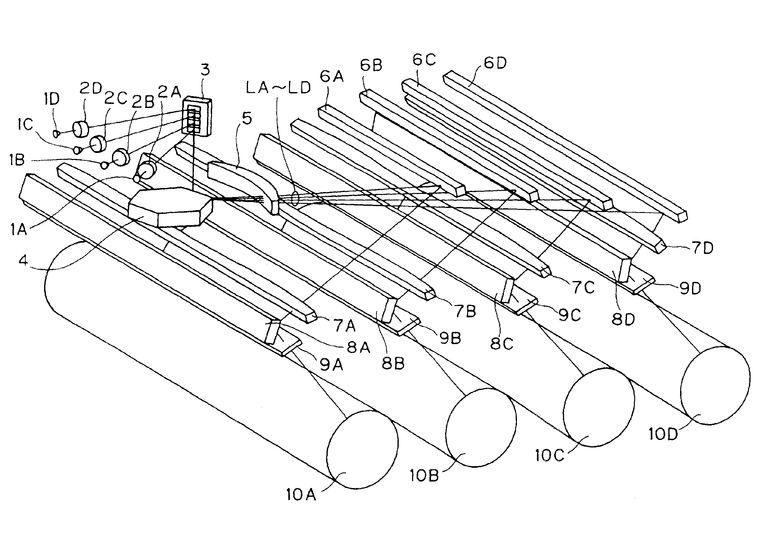
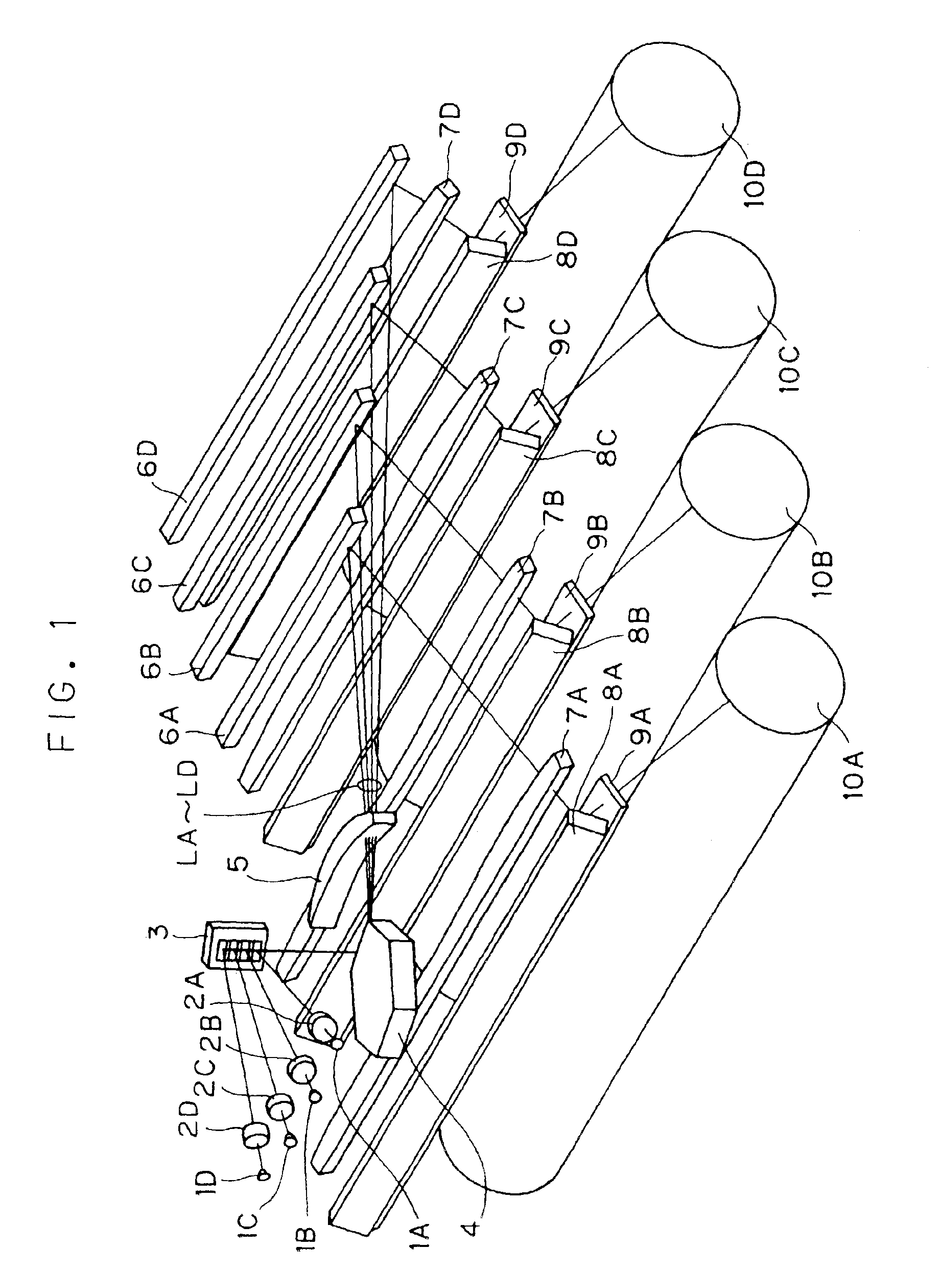
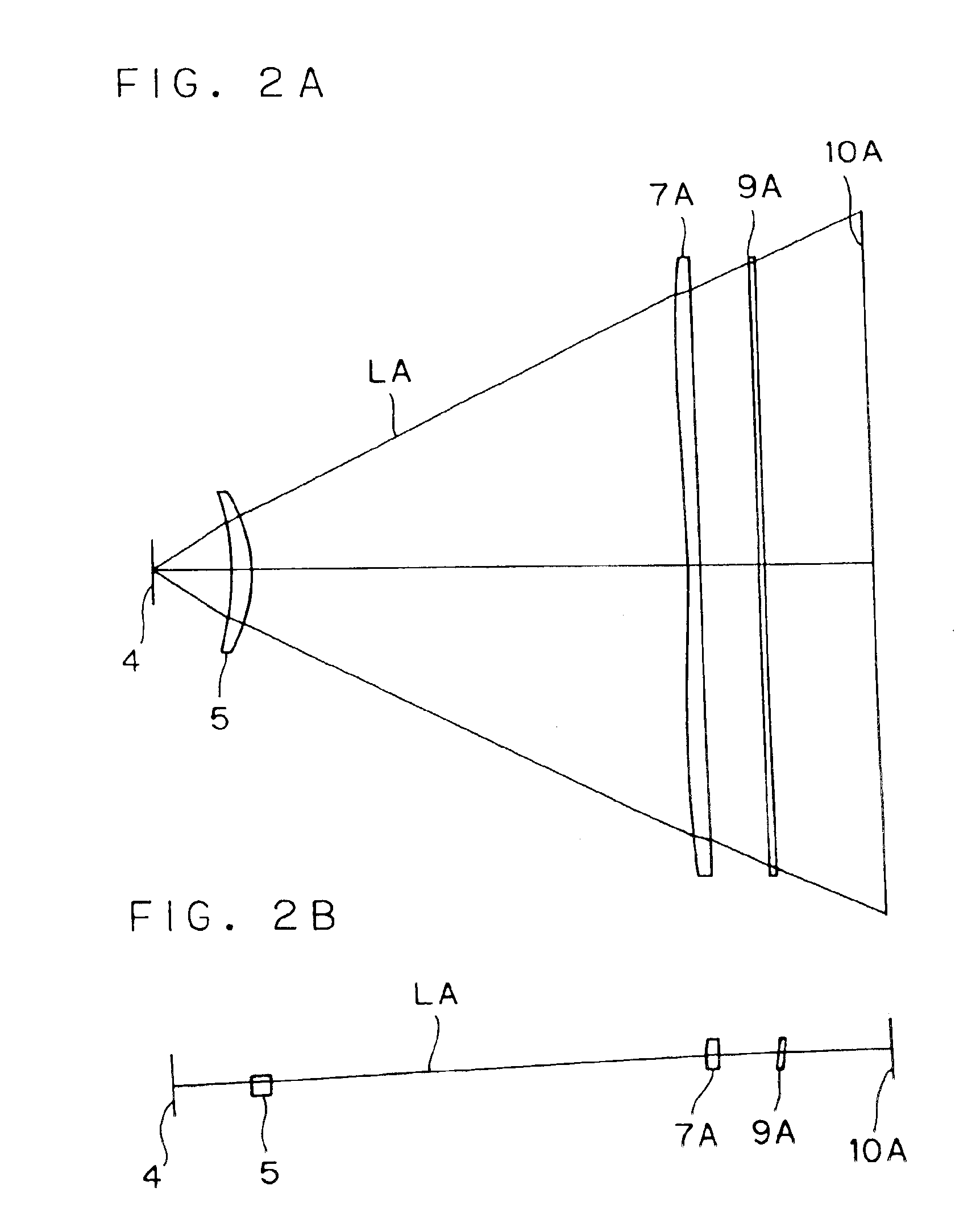
Hereinafter, laser scanning apparatuses embodying the present invention will be described with reference to the drawings. FIG. 1 shows a tandem-type laser scanning apparatus (Practical Example 1) embodying the invention for use in a color image formation apparatus (for example, a color laser printer, color digital copier, or the like). In FIG. 1, reference symbols 1A to 1D represent laser diodes, reference symbols 2A to 2D represent collimator lenses, reference symbol 3 represents a free-form-surface mirror array, reference symbol 4 represents a polygon mirror, reference symbol 5 represents a first lens, reference symbols 6A to 6D represent first turning mirrors, reference symbols 7A to 7D represent second lenses, reference symbols 8A to 8D represent second turning mirrors, reference symbols 9A to 9D represent window glass plates, reference symbols 10A to 10D represent photoconductors that provide scanned surfaces, and reference symbol LA to LD represent laser beams. In this laser s...


PUM


Abstract

A tandem-type laser scanning apparatus has a deflector for deflecting a first laser beam and a second laser beam, which fulfill prescribed conditions, in the main scanning direction by reflecting the laser beams simultaneously with a single surface and a scanning optical system for directing the deflected first and second laser beams to separate scanned surfaces corresponding thereto in such a way that the scanned surfaces are individually scanned with the laser beams focused thereon. The scanning optical system includes a common lens that has no curvature in the sub scanning direction and that transmits both the first and second laser beams, a first scanning lens that transmits, of the first and second laser beams transmitted through the common lens, the first laser beam but not the second laser beam, and a second scanning lens that transmits, of the first and second laser beams transmitted through the common lens, the second laser beam but not the first laser beam. The first and second scanning lenses each have a surface having a different twist from each other.

Description

This application is based on Japanese Patent Application No. 2002-232391 filed on Aug. 9, 2002, the contents of which are hereby incorporated by reference.BACKGROUND OF THE INVENTION1. Field of the InventionThe present invention relates to a tandem-type laser scanning apparatus, and more specifically to a tandem-type laser scanning apparatus that is used in an image formation apparatus such as a color laser printer or color digital copier to record an image on a plurality of scanned surfaces by scanning them with a plurality of laser beams in such a way that the scanned surfaces are individually exposed to the laser beams.2. Description of the Prior ArtU.S. Pat. No. 6,304,360 proposes a tandem-type laser scanning apparatus that forms a color image fast by scanning a plurality of photoconductors with a plurality of laser beams directed thereto by being deflected with a single deflector in such a way that the photoconductors are individually exposed to the laser beams.The laser scanni...

Claims


Application Information

Patent Timeline
Patent Type & Authority Patents(United States)
IPC IPC(8): G02B26/12G02B13/00B41J2/44G02B13/18G02B26/10H04N1/113
CPCG02B26/123
Inventor INAGAKI, YOSHIHIRO
Owner MINOLTA CO LTD
Why Eureka
Try Eureka