
Zoom lens

a zoom lens and zoom factor technology, applied in the field of zoom lenses, can solve the problems of simple conversions by means of known optical computing programs, and it is impossible to create other characteristics of the said zoom lens by a few, and achieve the effects of large zoom factor, large spectral range, and high imaging quality

Inactive Publication Date: 2005-02-15
CARL ZEISS OPTRONICS
View PDF10 Cites 4 Cited by
  • Summary
  • Abstract
  • Description
  • Claims
  • Application Information

AI Technical Summary

Benefits of technology

[0014]Such an arrangement can be used to implement the special characteristics for a zoom lens for military reconnaissance, the result being a zoom lens of high imaging quality, compact installation space because of the angle α, large zoom factor and large spectral range.
[0016]The refractive powers, of the two groups of the base lens group are to be selected such that as large an air space as possible is permitted between the two groups. The air space should be at least 15% of the installed length of the zoom lens. It is thereby possible that a beam deflector can be introduced into this air space, and thus that an installation space as small and compact as possible is created.

Problems solved by technology

It is also impossible to create other characteristics for the said zoom lenses by a few and simple conversions by means of known optical computing programs.

Method used


Image

  • Zoom lens
  • Zoom lens
  • Zoom lens

Examples


Embodiment Construction

section); and

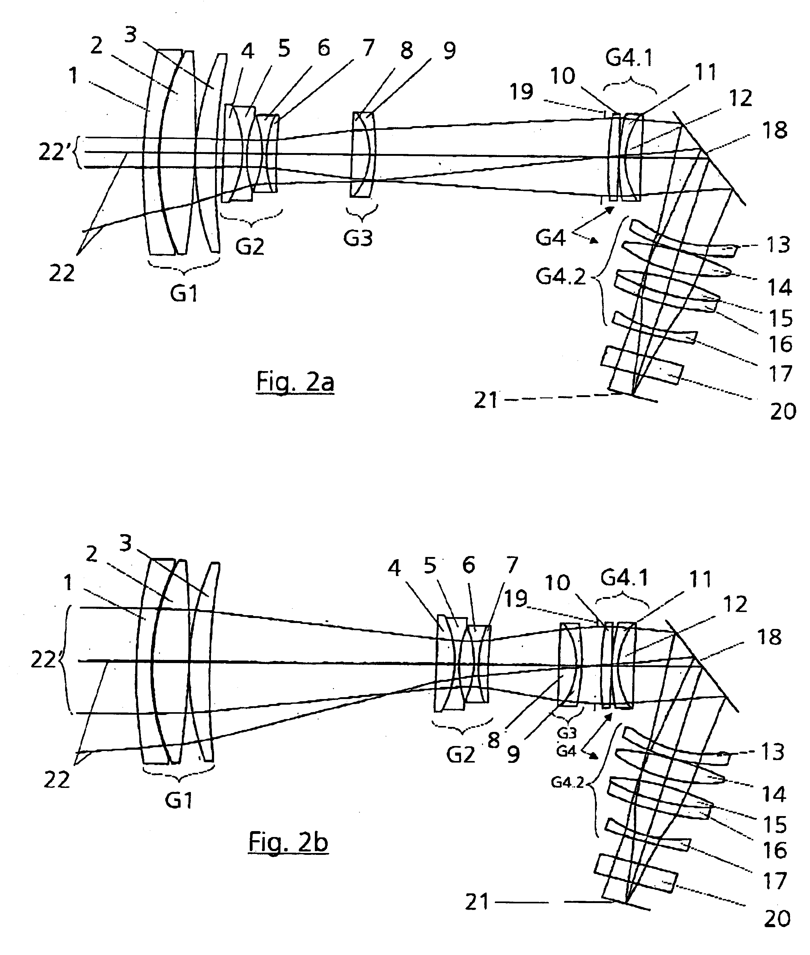
[0020]FIGS. 2a to 2c show a lens section of a zoom lens of three focal length settings, where[0021]FIG. 2a corresponds to f=34 mm;[0022]FIG. 2b corresponds to f=122 mm and[0023]FIG. 2c corresponds to f=272 mm.

DETAILED DESCRIPTION

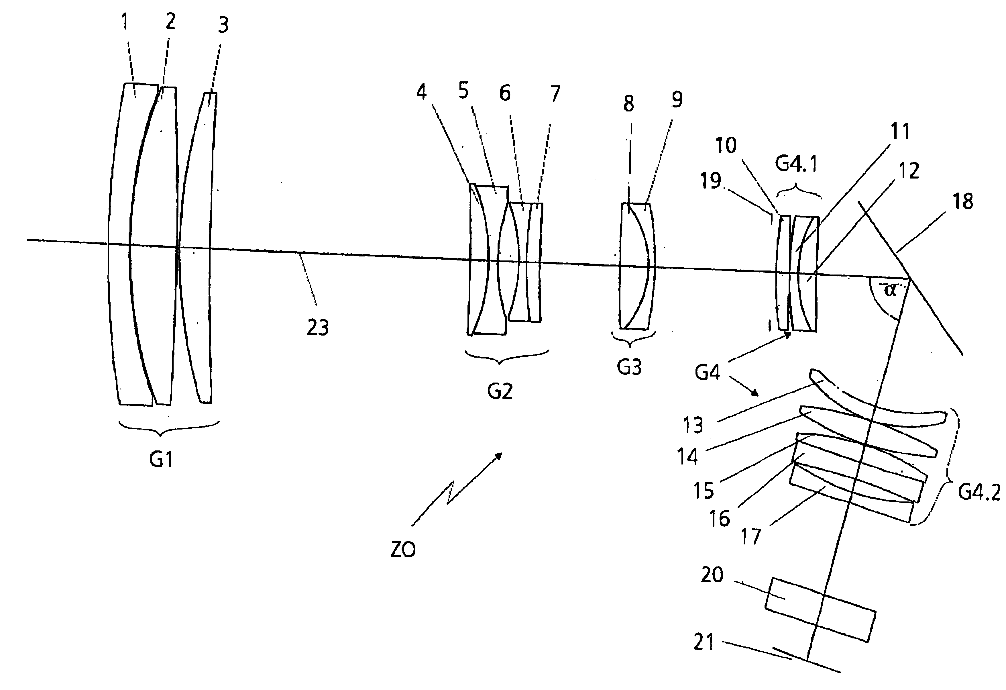
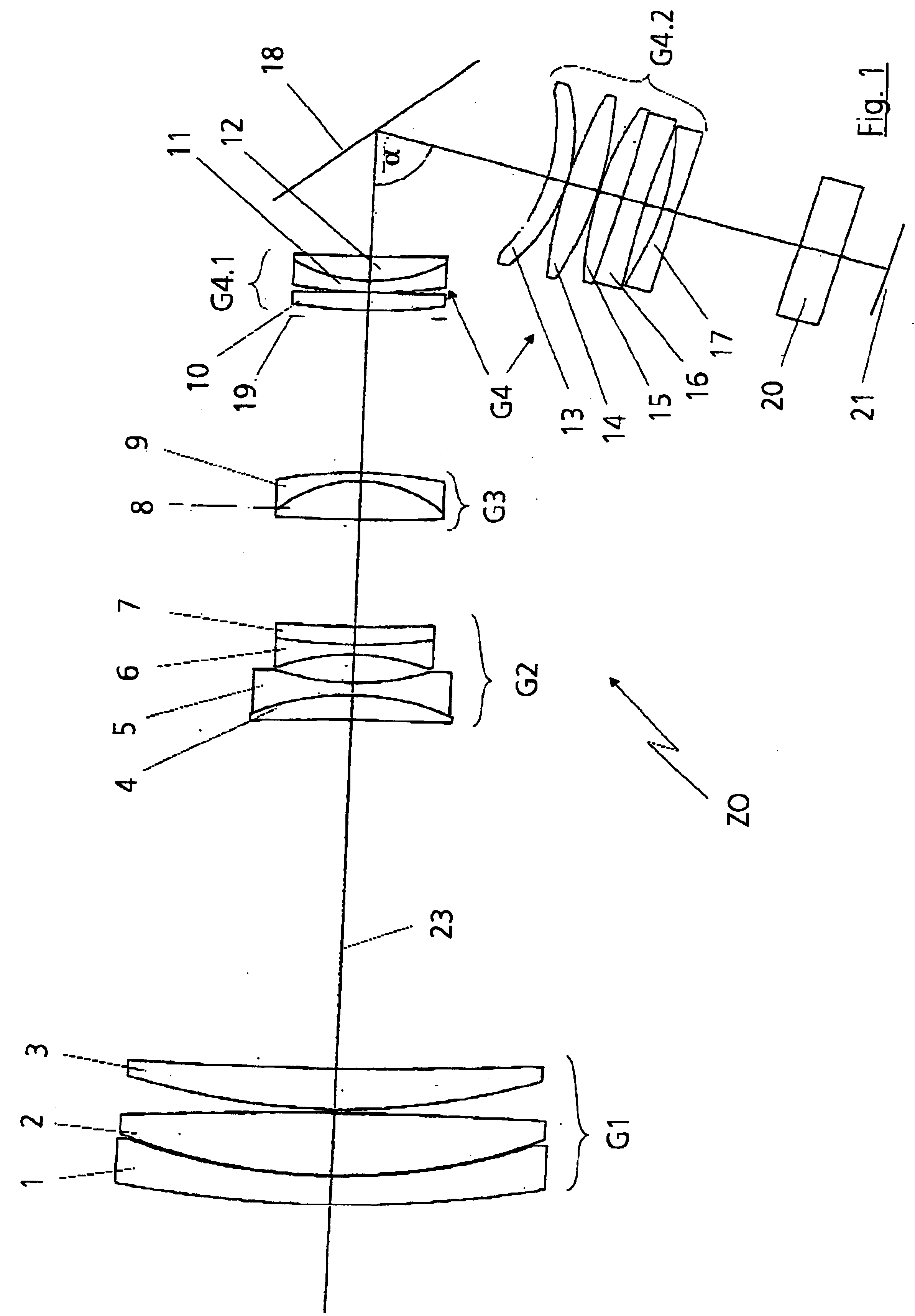
[0024]FIG. 1 shows an illustration of the principle of an inventive zoom lens ZO in lens section for military reconnaissance. The zoom lens ZO comprises a front lens group G1 of positive refractive power, a variator lens group G2 of negative refractive power, a compensator lens group G3 of positive refractive power, a base lens group G4 of positive refractive power and an optical spectral filter 20. The front lens group G1 is constructed from a negative lens 1 and two positive lenses 2 and 3. The negative lens 1 and the positive lens 2 are a split cemented component. This is advantageous because of the large difference in the coefficient of thermal linear expansion a of the two lenses 1 and 2. The positive lenses 2 and 3 are made from FluorCrown...


PUM


Abstract

A zoom lens comprises in a direction of light propagation a front lens group (G1) having positive refractive power, a variator lens group (G2) having negative refractive power, a compensator lens group (G3) having positive refractive power, and a base lens group (G4) having positive refractive power. The base lens group (G4) comprises a first base lens group (G4.1) and a second base lens group (G4.2). The front lens group (G1), the variator lens group (G2), the compensator lens group (G3) and the first base lens group (G4.1) are arranged along a common straight first optical axis (23). The second base lens group (G4.2) is arranged along a second optical axis 23′) inclined with respect to the first optical axis (23) at a first angle α different from 0° and 180°. A beam deflector (18) is arranged between the first base lens group (G4.1) and the second base lens group (G4.2).

Description

BACKGROUND OF THE INVENTION[0002]1. Field of the Invention[0003]The invention relates to a zoom lens comprising in a direction of light propagation a front lens group having positive refractive power, a variator lens group having negative refractive power, a compensator lens group having positive refractive power, a base lens group having positive refractive power.[0004]Numerous zoom lenses are already known from the prior art. The zoom lenses must fulfil specific optical and / or mechanical properties, depending on requirement.[0005]2. Description of the Related Art[0006]Zoom objectives for photography typically have a zoom factor of 2 to 4. The exit pupil vision is not telecentrically configured here. The installed length is to be kept as short as possible with these zoom lenses.[0007]Furthermore, zoom lenses for video recordings, for example camcorders, are known from the general prior art. The CCD detectors used in this case have an image diameter of at most 11 mm. The zoom factor...

Claims


Application Information

Patent Timeline
IPC IPC(8): G02B13/22G02B15/163G02B15/173
CPCG02B15/173G02B13/22G02B15/144113
Inventor ACHTNER, BERTRAM
Owner CARL ZEISS OPTRONICS
Learn More