Windshield wiper device

a technology for windshield wipers and wiper arms, which is applied in the field can solve the problems of invisibly low -off or non-operational state increase the cost of windshield wiper devices, and wiper arms

Inactive Publication Date: 2005-02-22
ROBERT BOSCH GMBH
View PDF8 Cites 36 Cited by
  • Summary
  • Abstract
  • Description
  • Claims
  • Application Information

AI Technical Summary

Benefits of technology

The technical effect of this patent is that it provides ways to keep certain parts securely attached to their designated positions on vehicles during operation. This helps ensure proper functioning of these components without causing any issues while driving or operating other safety features like windshield wipers.

Problems solved by technology

The technical problem addressed in this patent is how to improve a windshield wiper device by reducing the number of components needed for the wiper arm and making it more stable and cost-effective while also allowing for better lowering of the wipper blades into an invisible position.

Method used


Image

  • Windshield wiper device
  • Windshield wiper device
  • Windshield wiper device

Examples


Embodiment Construction

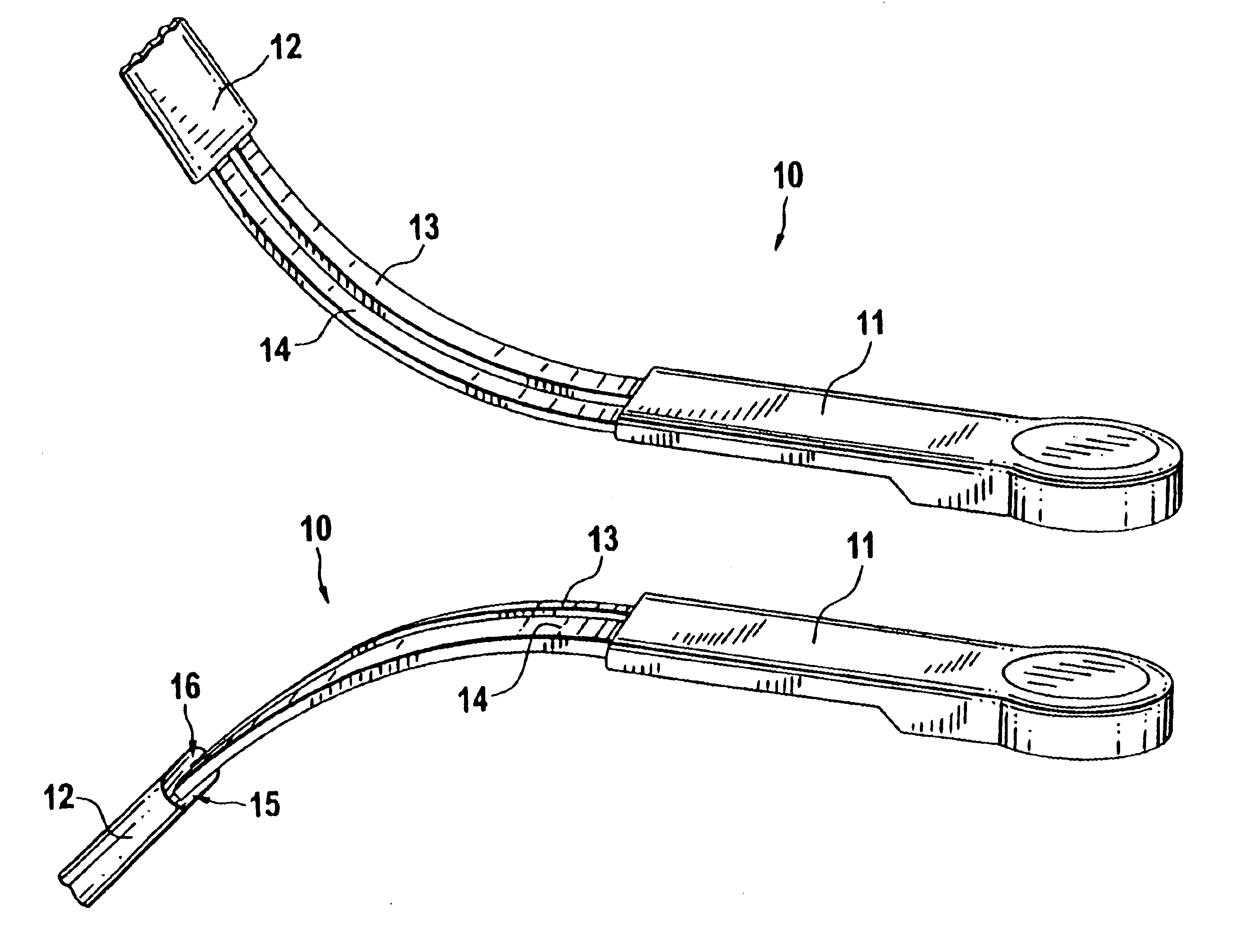
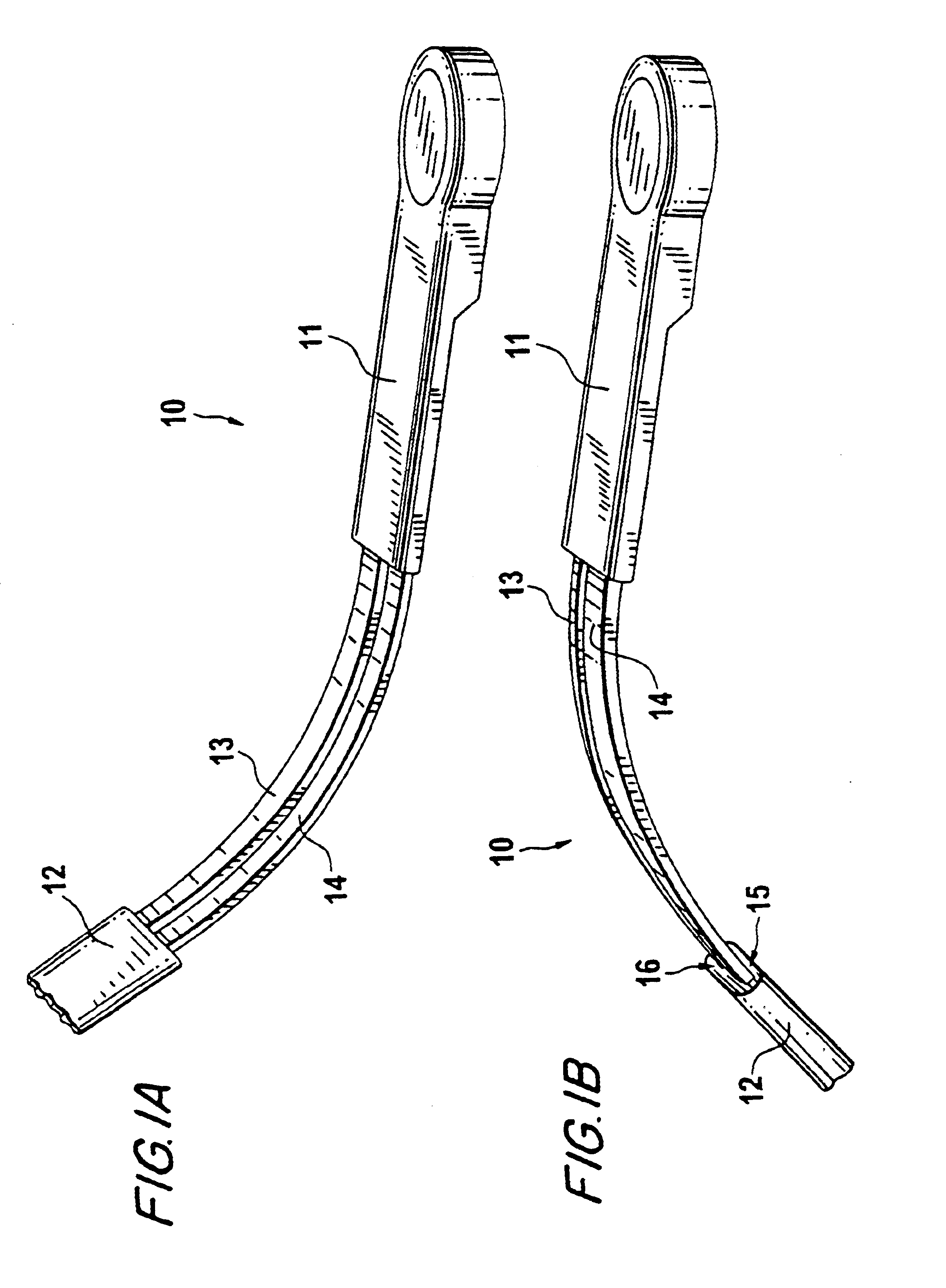
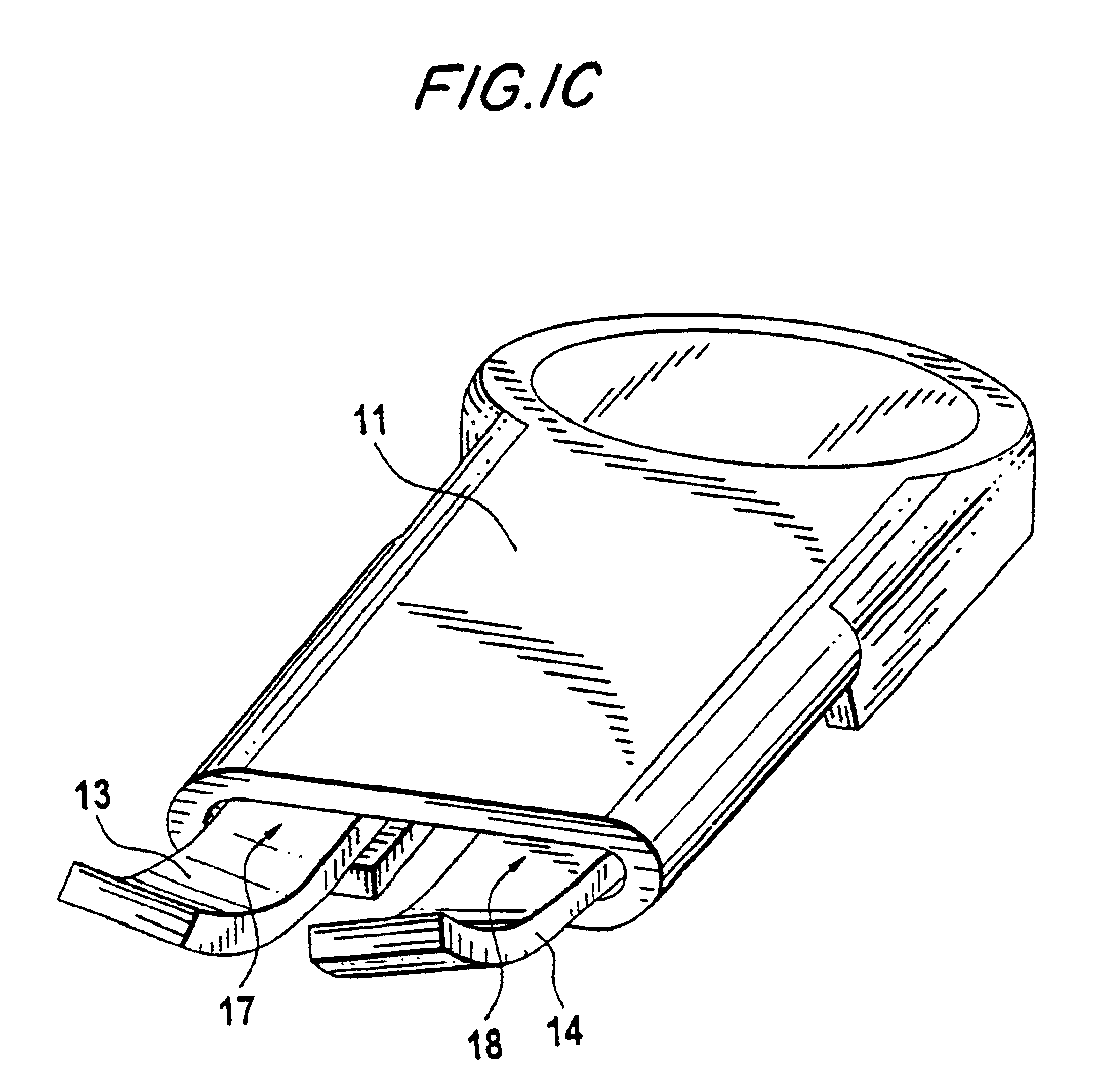
FIG. 1A shows a wipe arm 10 in a state of being folded out and away from the windshield, whereby the windshield is not specifically illustrated here. The wiper arm 10 has a region 11 facing a drive (not shown) and a region 12 facing a wiper blade (also not shown). Between the regions 11 and 12, two, spaced-apart torsion spring elements 13 are located. The torsion spring elements 13 have opposed torsion angles, so that the torsion spring elements 13 are rotated about their longitudinal axes (see FIG. 1C). By means of the two opposed torsion angles of the torsion spring elements 13, the torsion spring elements 13 experience a bending moment in their longitudinal direction, so that the wiper arm 10 obtains the longitudinal bend or curve illustrated in FIG. 1A or FIG. 1B. If one folds the wiper arm 10 that is folded out and away from the windshield (see FIG. 1A) against the windshield (see FIG. 1B), the opposed torsion angles of the torsion spring elements 13 and 14 are transposed, that...


PUM


Abstract

A windshield wiper device, in particular for a motor vehicle, includes a wiper arm (10) that is drivable by a drive, the wiper arm (10) being foldable onto the windshield and able to be folded away from the windshield. The wiper arm is associated with a wiper blade, whereby the wiper arm (10) has a region (11) that faces toward the drive and a region (12) that faces toward the wiper blade. Both regions are connected to two torsion spring elements (13, 14). The torsion spring element (13, 14) are provided with two opposite torsion angles. The torsion spring elements (13, 14) have a square cross section, whose width is greater than its thickness, so that the torsion spring elements (13, 14) are curved in a longitudinal direction toward the windshield or curved away from the windshield.

Description


Claims


Application Information

Patent Timeline
Owner ROBERT BOSCH GMBH
Why Eureka
Try Eureka