Header Tank for Heat Exchanger

a heat exchanger and header technology, applied in indirect heat exchangers, light and heating apparatus, other domestic objects, etc., can solve the problems of increasing component cost, increasing assembly cost, and unable to avoid cost increase, so as to reduce manufacturing cost, reduce component cost, and reduce assembly cost

Inactive Publication Date: 2007-11-08
CALSONIC KANSEI CORP
View PDF9 Cites 28 Cited by
  • Summary
  • Abstract
  • Description
  • Claims
  • Application Information

AI Technical Summary

Benefits of technology

[0021] According to the first aspect of the present invention, the refrigerant distribution groove is formed in the tank lower portion, and the refrigerant communication holes are provided for the refrigerant distribution groove. Moreover, the opening is closed by the plate portion to form the refrigerant distribution passage. Such a structure eliminates the need to manufacture a refrigerant distribution pipe, a holding plate, and the like as separate components, thus reducing component cost. Such a structure eliminates the need for a process to attach the refrigerant distribution pipe, holding plate, and the like to the inside of the tank, thus reducing assembly cost. Accordingly, the lower header tank 13 has the same function as a header tank including the refrigerant distribution pipe inside while further reducing manufacturing cost. The integration of the refrigerant distribution portion and the tank lower portion prevents occurrence of distortion in the refrigerant distribution groove due to the temperature difference during brazing and prevents reduction of the distribution efficiency due to the distortion within the tank as is observed in the refrigerant distribution pipe.
[0022] According to the second aspect of the present invention, the lower tank lower and the refrigerant distribution portion with a substantially circular section are integrally formed, and the refrigerant communication holes are formed in the refrigerant distribution portion. Such a structure eliminates the need to manufacture the refrigerant distribution pipe, holding plate, and plate as separate components, thus reducing component cost. Such a structure eliminates the need for a process to attach the refrigerant distribution pipe, holding plate, and the like to the inside of the tank, thus reducing assembly cost. Accordingly, this structure has the same function as that of the header tank including the refrigerant distribution pipe inside while further reducing the manufacturing cost. Integration of the tank lower portion and refrigerant dis

Problems solved by technology

However, the header tank including the refrigerant distribution pipe inside requires the refrigerant distribution pipe and a holding plate holding the same, increasing component cost.
Moreover, the header tank requires a process to attach these components to the inside of the header tank, increasing assembly cost.
Accordingly, the aforementioned related example cannot avoid an increase in cost.
When

Method used


Image

  • Header Tank for Heat Exchanger
  • Header Tank for Heat Exchanger
  • Header Tank for Heat Exchanger

Examples


first embodiment

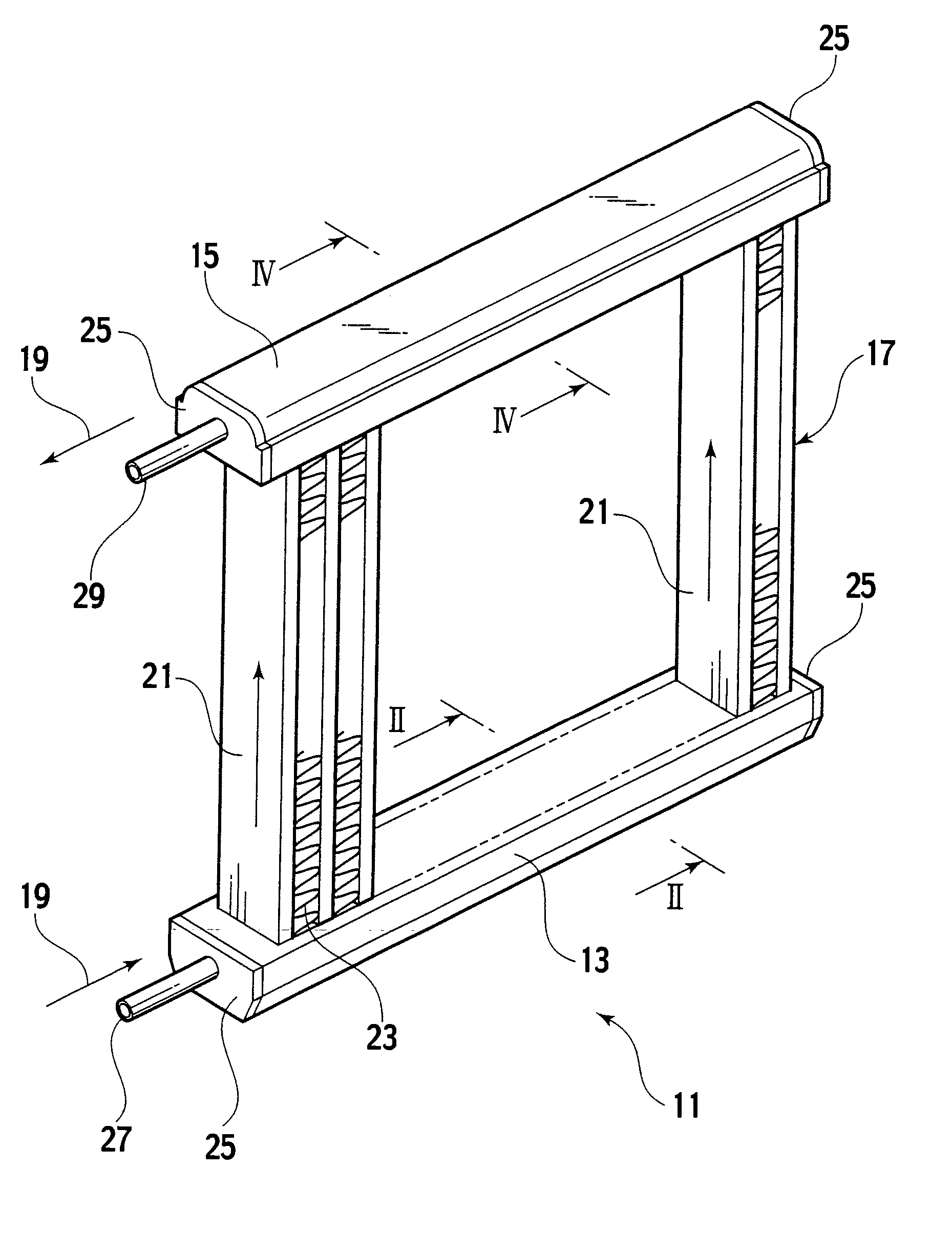
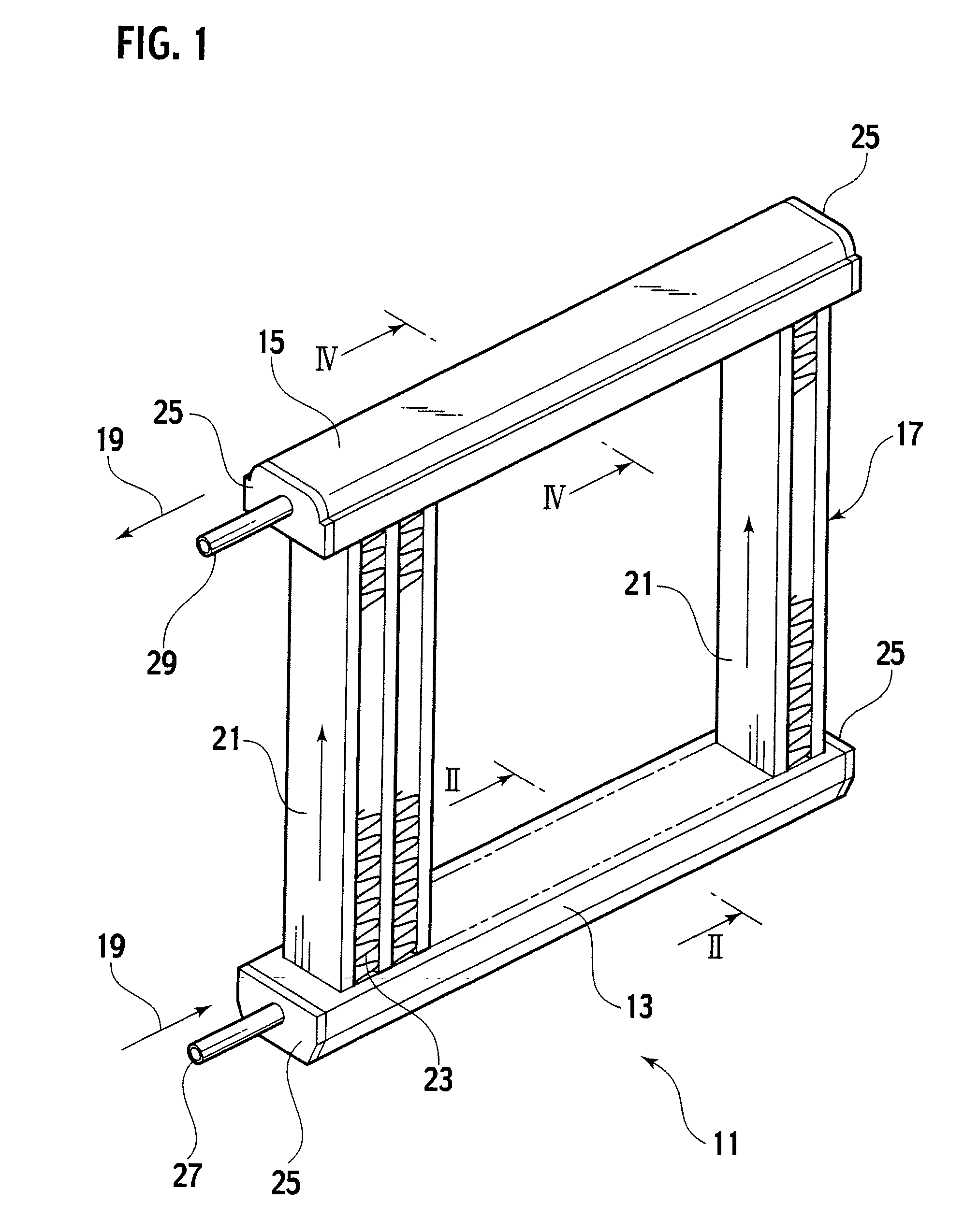
[0051]FIG. 1 is an external perspective view showing an entire structure of a heat exchanger according to an embodiment. A heat exchanger 11 roughly includes a lower header tank 13, an upper header tank 15, and a heat exchanger core 17. The heat exchanger core 17 includes a plurality of tubes 21, through which refrigerant 19 flows, and cooling fins 23. The tubes 21 and cooing fins 23 are alternately arranged. The lower end of the heat exchanger core 17 is connected to the lower header tank 13 and communicates with an end of each tube 21. The upper end of the heat exchanger core 17 is connected to the upper header tank 15 and communicates with the other end of each tube 21.

[0052] Both ends of the lower header tank 13 are closed by end plates 25. One of the both ends is connected to an inlet pipe 27, which supplies the refrigerant 19. The both ends of the upper header tank 15 are also closed by end plates 25. One of the both ends is connected to an outlet pipe 29, which discharges th...

second embodiment

[0069] Next, a description is given of a structure of a lower header tank 73 according to a second embodiment. Hereinafter, portions equivalent to those of the first embodiments are indicated by same reference numerals, and redundant descriptions of the structure and operational effects are properly omitted.

[0070]FIG. 5 is a cross-sectional view showing a structure of the lower header tank 73, which corresponds to a cross-sectional view along II-II of FIG. 1. This lower header tank 73 includes a lower tank upper 51 and a lower tank lower 53.

[0071] The lower tank upper 51 as a tank constituent member is shaped to have a square U-shaped section by bending both ends of a plate material. The flat part thereof includes tube insertion holes 51a for connection of tubes 21. The tube insertion holes 51a are formed at regular intervals along the longitudinal direction. The lower tank lower 53 is shaped to have a Q-shaped section by bending (or extruding) center part of a plate material, thu...

third embodiment

[0078]FIG. 7 is a cross-sectional view showing a structure of a lower header tank 83 according to a third embodiment, which corresponds to a cross-sectional view along II-II of FIG. 1. The lower header tank 83 is formed into a tubular shape with a square section by bending a single plate material or a single pipe material (in the case of the plate material, joining the seam after bending). Flat part in the upper face includes tube insertion holes 61a for connection of the tubes 21. The tube insertion holes 61a are formed at regular intervals in the longitudinal direction. The center part in the lower face is shaped to have a Q-shaped section, thus integrally forming a refrigerant distribution portion 63A with a circular section with the body of the lower header tank 83.

[0079] The refrigerant distribution portion 63A includes a plurality of refrigerant communication holes 63a and 63b in the longitudinal direction. Among these, the communication holes 63a allow passage of refrigerant...


PUM

PropertyMeasurementUnit
Diameteraaaaaaaaaa
Currentaaaaaaaaaa
Thicknessaaaaaaaaaa

Abstract

A header tank for a heat exchanger includes tank forming sections that are joined into a tubular shape with a substantially square cross-section. The header tank has a refrigerant low path formed inside the tank forming sections include a tank upper section (31) in which tube insertion holes (31a) for connecting tubes of a heat exchanger core are formed. The tank lower section (33) having a substantially U-shaped refrigerant split-flow groove (33A) that has, in its longitudinal direction, communication holes (33a, 33b) for the refrigerant. The tank forming sections include a plate section (35) for closing an opening of the refrigerant split-flow groove (33A) to form a refrigerant split-flow path (37) inside the tank lower section.

Description

TECHNICAL FIELD [0001] The present invention relates to a header tank for a heat exchanger used in vehicles and the like and specifically relates to a structure of a header tank having a function to equally distribute refrigerant to each tube. BACKGROUND ART [0002] A general heat exchanger used in vehicles and the like includes a heat exchanger core having flat tubes and fins alternately arranged and header tanks causing refrigerant to flow into the heat exchanger core. The header tanks among these are separated into an inlet header tank and an outlet header tank. The inlet header tank causes externally supplied refrigerant to flow into each tube of the heat exchanger core. The outlet header tank joins together flows of refrigerant which has exchanged heat with cooling air while passing through the tubes of the heat exchanger core and discharges the same to the outside. The arrangement of the header tanks includes various types depending on path of refrigerant, and a general structu...

Claims


Application Information

Patent Timeline
IPC IPC(8): F28F9/02
CPCF25B39/04F28F9/02Y10T29/49389F28F9/0273F28F9/0214
Inventor MASHIKO, SEIJIUEBAYASHI, KAZUTAKAIKUIA, SHIRO
Owner CALSONIC KANSEI CORP
Why Eureka
Try Eureka