Aircraft door hinge assembly

a technology for aircraft doors and hinges, applied in the field of hinges, can solve the problems of difficult maneuverability and/or striking the door would swing free at the end of the hinge, and the epas would be difficult to move and/or strike the outer skin of the fuselage, etc., to achieve simple components, reduce the cost of epas components, and reduce or eliminate problems

Active Publication Date: 2006-09-14
THE BOEING CO
View PDF9 Cites 44 Cited by
  • Summary
  • Abstract
  • Description
  • Claims
  • Application Information

AI Technical Summary

Benefits of technology

[0009] A pivot fitting positioned closest to the door structure attachment pin provides an interface point for the Emergency Power Actuation System (EPAS) / Snubber cylinder. The inclusion of the EPAS / snubber system in this manner should allow for simplification and possibly reduced costs of the EPAS components. The invention incorporates a concept where the EPAS cylinder and the door snubber are combined into one component serving both purposes.
[0010] The hinge assembly of the present invention provides the necessary motion control for the door structure through the opening motion. At all times, it controls the relative orientation of the door structure to the aircraft body, and rigidly constrains the door while in the fully open position. The mechanism provides for a smooth translating motion through the use of length-adjustable links, pins, and pivot fittings.
[0011] The mechanism of the present invention reduces or eliminates problems typically associated with chain systems, such as tensioning, lubrication and corrosion.
[0012] Advantageously, the present invention includes relatively simple components, such as simple and common rods, pins, small machined fittings, bushings, and bearings. Thus, the need for complex machining or manufacturing practices is reduced or eliminated.
[0013] The present invention provides a lighter design, fewer components, reduced component costs, reduced rigging requirements at installation, greater control of door structure(reduced door play throughout motion travel), than chain-type systems. Overall, the mechanism of the present invention is less complex, and easier to fabricate and install than chain-type systems.

Problems solved by technology

If the movement of the door was not controlled, the door would swing free at the end of the hinge and be difficult to maneuver and / or strike the outer skin of the fuselage.

Method used


Image

  • Aircraft door hinge assembly
  • Aircraft door hinge assembly
  • Aircraft door hinge assembly

Examples


Embodiment Construction

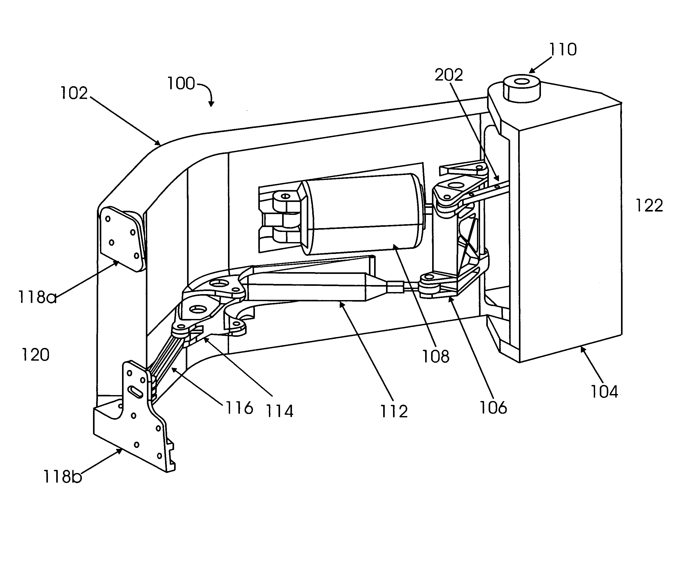
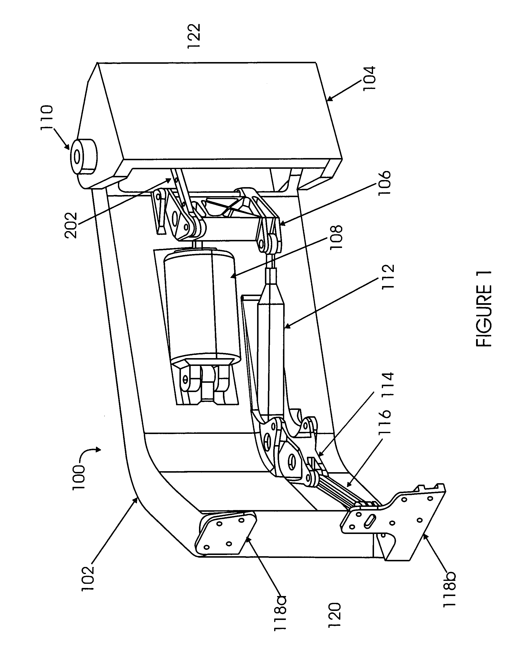
[0020]FIG. 1 is a perspective view of a hinge assembly 100 in accordance with an embodiment of the present invention. Hinge assembly 100 includes components which allow it to perform in its intended manner. Many of these components are common to mechanical systems, such as pins, fasteners, brackets and the like. The following description shall describe selected components and their arrangement and combination needed to understand the invention.

[0021] Hinge assembly 100, includes hinge member 102 which provides the structural support member that connects a door structure (not shown) to an aircraft fuselage (not shown). In one embodiment, hinge member 102 includes two primary pivot points: 1) between hinge member 102 and the aircraft fuselage at end 120 and 2) between hinge assembly 100 and the door structure at the end 122.

[0022] Hinge member 102 provides the attach points for the remaining components of hinge assembly 100. For example, mounted to hinge member 102 are door-to-hinge...


PUM


Abstract

A hinge assembly for attaching a door structure to an aircraft fuselage is provided. The door structure is linked to the aircraft body structure by way of a programmable mechanical linkage that is attached to the hinge member. The programmable mechanical linkage is actuated along the hinge member so as to maintain the door structure attached thereto in a controlled angular relationship relative to the longitudinal axis of the aircraft fuselage through its attachment to the fixed aircraft frame.

Description

BACKGROUND [0001] 1. Field of the Invention [0002] This invention relates generally to aircraft door assemblies and, more particularly, to a hinge mechanism for connecting an aircraft door to a fuselage. [0003] 2. Related Art [0004] An important part of any door assembly is the hinge assembly that connects the door to the adjacent aircraft fuselage structure. One particular type of hinge assembly is arranged so that, when the door is opened, the door physically separates from the surrounding structure and is translated out and away from the body while the door itself maintains a relatively parallel orientation to the longitudinal axis of the aircraft fuselage. The hinge also translates the door forward to provide a clear opening into the aircraft as the door swings away from the body. When the door is completely open, the inside face of the door is adjacent the outer skin of the aircraft. [0005] Many hinge assemblies used with translating-motion-type aircraft doors include both a st...

Claims


Application Information

Patent Timeline
Patent Type & Authority Applications(United States)
IPC IPC(8): B64C1/14
CPCB64C1/1407E05D3/06E05D3/12E05F5/00E05Y2900/502
Inventor MORTLAND, MICHAEL T.
Owner THE BOEING CO
Why Eureka
Try Eureka