Plastic Optical Member and Producing Method Thereof

a technology of optical components and manufacturing methods, applied in the field of plastic optical components, can solve the problems of reducing manufacturing efficiency, increasing manufacturing costs, and reducing manufacturing efficiency, and achieve the effects of easy production, easy production, and easy obtaining of complicated cross-sectional shapes

Inactive Publication Date: 2008-08-28
FUJIFILM CORP
View PDF7 Cites 28 Cited by
  • Summary
  • Abstract
  • Description
  • Claims
  • Application Information

AI Technical Summary

Benefits of technology

[0020]According to the method for producing the plastic optical member of the present invention, since the cross-sectional shape of the preform is non-circular, and the preform is heat-drawn to form the plastic optical member having the cross-sectional shape similar to that of the preform, the plastic optical member having fine structure can be easily produced without use of a special device.
[0021]Since the preform is a preform piece assembly constituted by assembling plural preform pieces, the preform having complicated cross-sectional shape can be easily obtained. Therefore, the plastic optical member having complicated cross-sectional shape can be easily produced. Since the preform piece assembly includes at least one secondary preform piece formed by heat-drawing the primary preform piece, the plastic optical member having more complicated cross-sectional shape can be easily produced. I

Problems solved by technology

The use of the special processing device corresponding to each type of optical member increases the manufacturing cost and decreases the manufacturing effic

Method used


Image

  • Plastic Optical Member and Producing Method Thereof
  • Plastic Optical Member and Producing Method Thereof
  • Plastic Optical Member and Producing Method Thereof

Examples


experiment 1

[0103](Experiment 1)

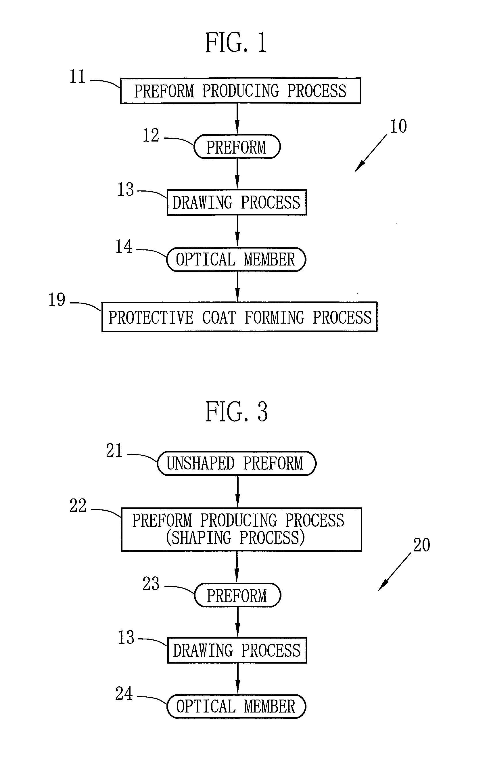
[0104]In experiment 1, an optical member 14a shown in FIG. 9C was obtained from preform 12 shown in FIG. 9B, by the first process 10 shown in FIG. 1. At first, as shown in FIG. 9A, a square pipe (hereinafter the clad pipe) 70 of 1000 mm length, which has 0.5 mm thickness and a cross-section whose sides L1 are 20 mm length, was provided. The clad pipe 70 became a clad 71a when the optical member 14a was obtained, for keeping transmitting light in a core 72a. The clad pipe 70 was formed of PVDF which is plastic having low refraction index. Note that in this experiment, the clad pipe 70 was formed by the melt-extrusion method.

[0105]Next, in the clad pipe 70, a core 72 was formed as shown in FIG. 9B. Although material of the core 72 is not limited while having optical transparency, it is preferable that optical transmission loss is low. In this experiment, PMMA which is (meth)acrylic acid resin was used. To form the core 72, methyl methacrylate (MMA) or the like was ...

experiment 2

[0106](Experiment 2)

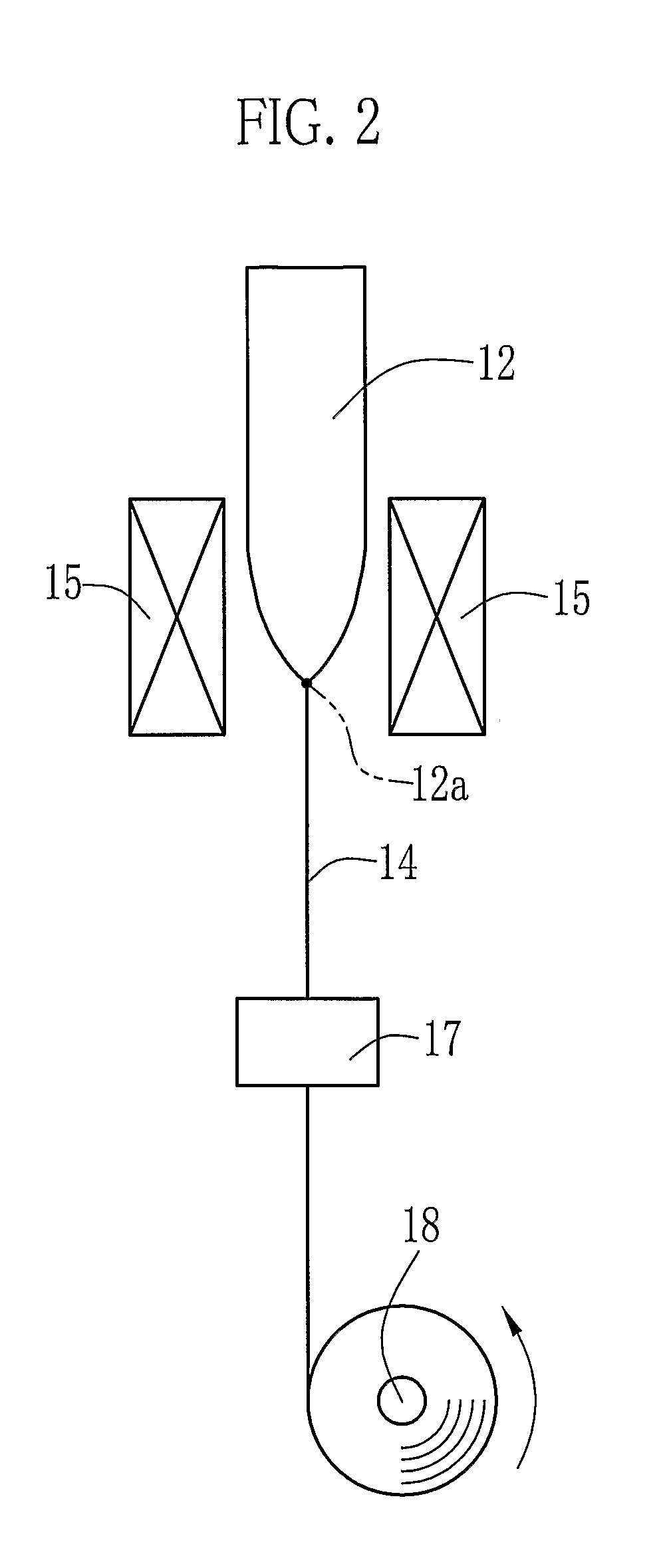
[0107]In experiment 2, an optical bus (sheet bus) which is the optical member 24 was produced by the second process 20 shown in FIG. 3. At first, as shown in FIG. 10A, a cylindrical unshaped preform 21, whose cross-section has the diameter L3 of 20 mm, was produced. The unshaped preform 21 comprises a core 80 and a clad 81. The clad 81 contains light scattering particles (silicon particles, whose average diameter is 1 μm). The core 80 mainly contains PMMA, and the clad 81 mainly contains PVDF. Next, as shown in FIG. 10B, the unshaped preform 21 was sandwiched between two flat plates 82 and 83, and was applied the heat-pressing process to be deformed, in 600 seconds at approximately 200° C. under approximately 0.5 MPa. As a result, the oval preform 23, whose cross-sectional ratio (L5:L4) is 1:4 (9.1 mm×36.4 mm) was obtained. Then in the drawing process 13 shown in FIG. 3, The preform 23 was heat-drawn in the temperature range of the softening point to the melting ...

experiment 3

[0108](Experiment 3)

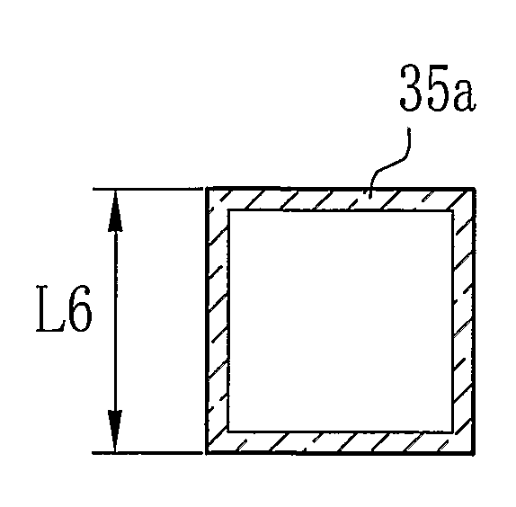
[0109]In experiment 3, an optical member 33a having four cores whose cross-section is square, as shown in FIG. 11E, was obtained by the third process 30 shown in FIG. 4. At first, in the clad pipe producing process 34 in the preform piece producing process 31, a square clad pipe 35a of PVDF, which has 1000 mm length, 0.5 mm thickness and a cross-section whose sides L6 are 10 mm length, was produced by the melt-extrusion. The clad pipe 35a was inserted in the polymerization container. After the polymerization container containing the clad pipe 12 was washed with pure water, the polymerization container was dried under the temperature of 90° C. Thereafter, one end of the clad pipe 35a was sealed by a Teflon (Registered Trademark) stopper. The inner wall of the clad pipe 35a was washed with ethanol, and then the clad pipe 35a was subject to decompression process (−0.08 MPa to atmospheric pressure) for 12 hours at 80° C. by an oven.

[0110]Next, an outer core polymeriz...


PUM


Abstract

A clad pipe (70) is produced by heating PVDF to 180° C., and then this PVDF being extruded from a melt-extrusion device. The clad pipe (70) has a square cross-section whose sides L1 are 20 mm length, and in a center thereof, there is a square hole. In the square hole, a core (72) mainly includes PMMA is formed. Accordingly, a preform (12) having a clad (71) of PVDF and the core (72) of PMMA is obtained. The preform (12) is heat-soften-drawn at 210° C. A drawing ratio is 1600. Finally, an optical member (14) having a 0.5 mm square cross-section is obtained.

Description

TECHNICAL FIELD[0001]The present invention relates to a plastic optical member and a method for producing the plastic optical member.BACKGROUND ART[0002]Recent development in communication industry, the demand for the plastic optical transmission medium with lower transmission loss and low manufacture cost has been increased. The plastic optical transmission medium has merits of design facility and low manufacture cost, compared with a silica glass optical transmission medium with identical structure. Especially, the plastic optical transmission medium, entirely composed of a plastic material, is suitable for producing an optical transmission medium with a large diameter at a low cost, because the plastic has advantages in excellent flexibility, light weight and high machinability, compared with the silica glass. Accordingly, it is planned to use the plastic optical transmission medium for short-distance purpose in which the transmission loss is small (for example, Japanese Laid-Ope...

Claims


Application Information

Patent Timeline
IPC IPC(8): G02B6/036B29D11/00
CPCG02B6/08B29D11/00663
Inventor WAKABAYASHI, AKIRANAKATA, SHUJINAKAMURA, YOSHISADAHIWATASHI, YUKA
Owner FUJIFILM CORP
Why Eureka
Try Eureka