
Collapsible display stand

a display stand and freestanding technology, applied in the field of display stands, can solve the problems of limiting the available floor space and best viewing angle, adding to the cost of the lamotte device, etc., and achieve the effects of improving adaptability to uneven surfaces, simple structure and low cos

Inactive Publication Date: 2005-02-22
BURRIS JEFF
View PDF14 Cites 21 Cited by
  • Summary
  • Abstract
  • Description
  • Claims
  • Application Information

AI Technical Summary

Benefits of technology

A collapsible display stand with a foot-and-bar base is disclosed. The foot-and bar base provides improved adaptability to uneven surfaces. The foot provides a flexible connection between a vertical support member and two adjustable strut braces. The strut braces have controllable sliding connections to two flexed struts. The point of closest approach of the struts may be constrained by a grommet, clamp, or sleeve and maintained a predetermined distance from the foot by a vertical support member. Also disclosed is a simplified, inexpensive apparatus for connecting strut ends to mounting tubes. The simplified appara...

Problems solved by technology

Different trade show locations may offer different limitations on available floor space and best viewing angle.
The detailed design of the connectors between the struts and the tubes adds to the cost of the LaMotte device.

Method used


Image

  • Collapsible display stand
  • Collapsible display stand
  • Collapsible display stand

Examples


Embodiment Construction

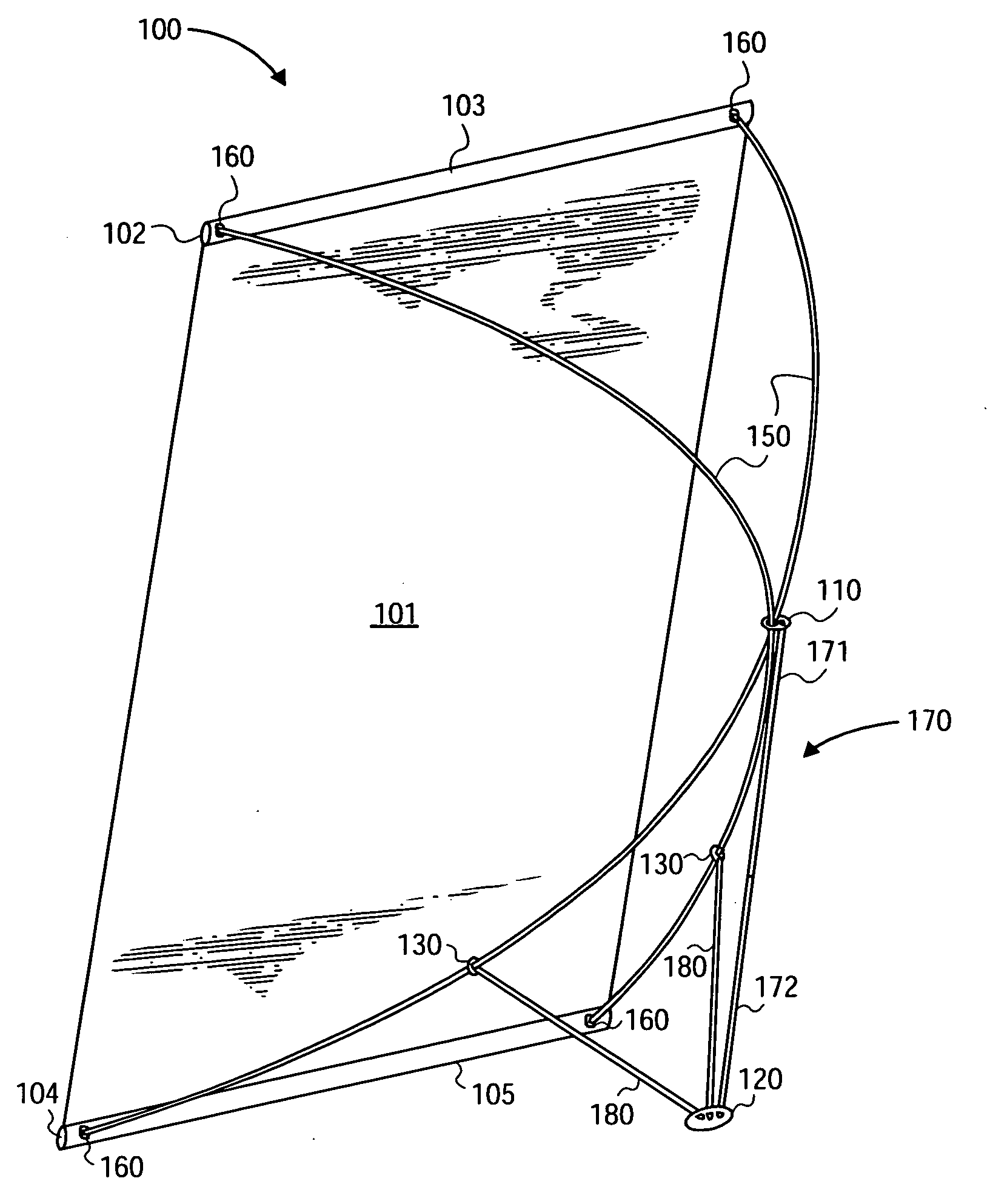
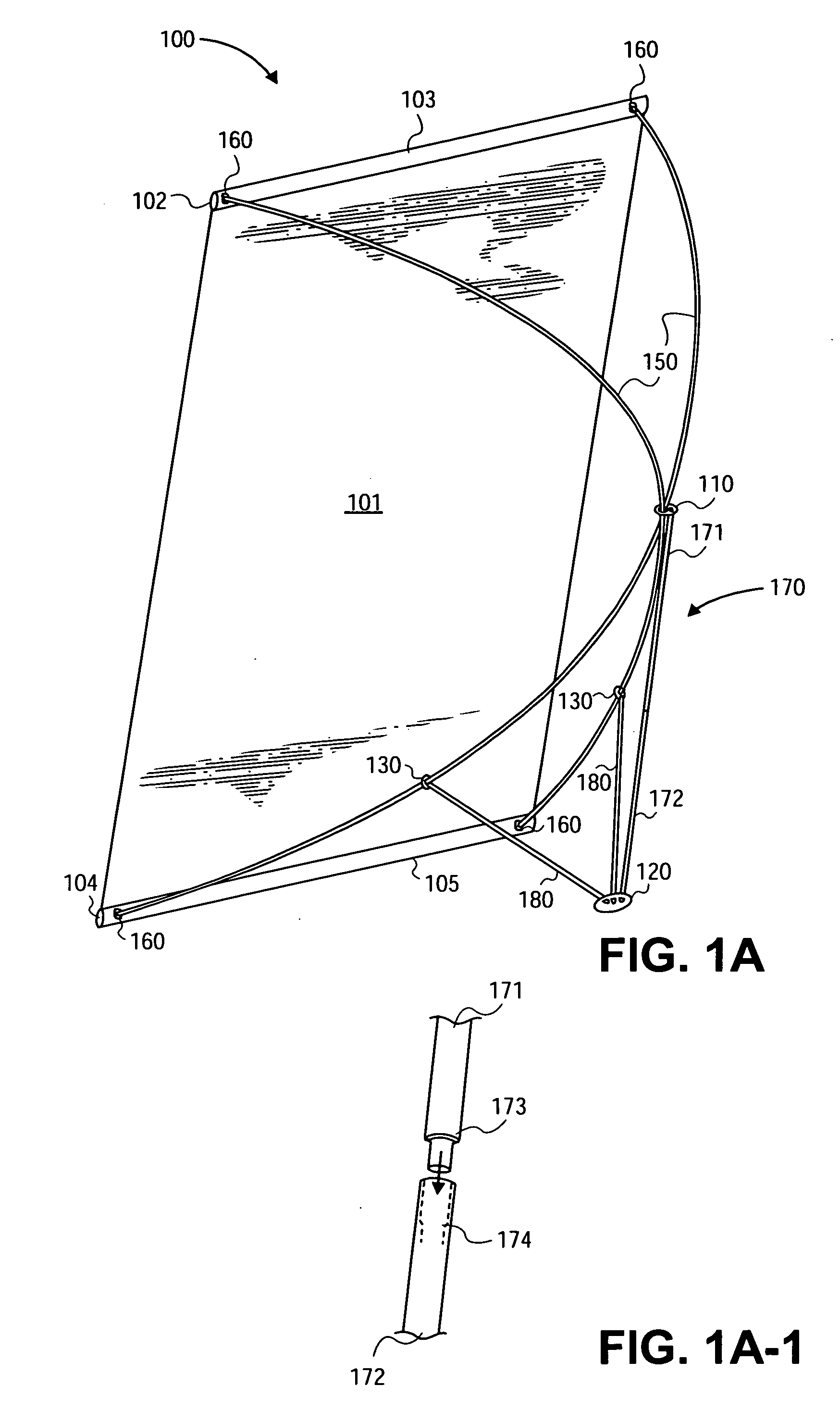
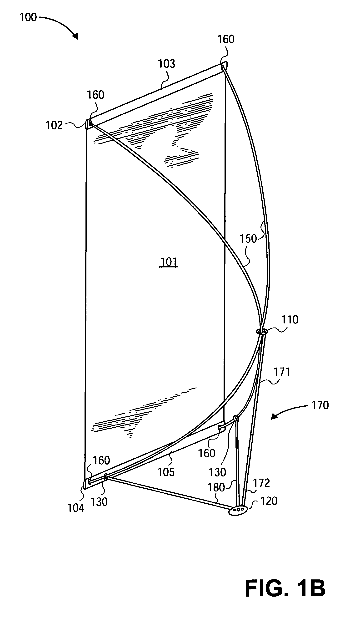
FIG. 1A shows an example of an embodiment of a collapsible display stand 100. Two bowed struts 150 maintain the panel 101, or banner 101, in tension. The panel 101 is conventionally flexible but may be rigid or resilient. Mounting tubes 102 and 104, conventionally inserted through sleeves 103 and 105, respectively, in the banner 101 ends, may receive a strut 150 end in a hole 160 through the side of the mounting tube 102 and 104 near each end of the mounting tube 102 and 104. In the embodiment shown in FIG. 1A, the strut-receiving holes 160 in the tube 102 and 104 side are aligned with holes 103 and 105, respectively, in the sleeve. (See also FIG. 3A).

In an alternate embodiment, the mounting tube 102 and 104 extends beyond the ends of the banner sleeves 103 and 105, the strut-receiving hole 160 is in the portion of the tube 102 and 104 extending outside the banner sleeve 103 and 105, and the banner sleeve 103 and 105 requires no holes. (See also FIG. 3B). The mounting tubes 102 and ...


PUM


Abstract

A collapsible display stand with a foot-and-bar base is disclosed. The foot-and-bar base provides improved adaptability to uneven surfaces. The foot provides a flexible connection between a vertical support member and two adjustable strut braces. The strut braces have controllable sliding connections to two flexed cross struts. The point of closest approach of the struts may be constrained by a grommet, clamp, sleeve, or motor bracket and maintained a predetermined distance from the foot by a vertical support member. Also disclosed is a simplified, inexpensive apparatus for connecting strut ends to mounting tubes. The simplified apparatus comprises a hole drilled in one side of the mounting tube near each mounting tube end, into which an unadorned strut end may be inserted. The foot, slidable strut brace connectors, and the point-of-closest-approach constraint may be economically made of hard rubber, such as that used in making mud flaps for trucks. The collapsible display stand may be adjusted by hand or, especially for very large embodiments, by motorized point-of-closest-approach and strut brace constraints. The motorized constraints may be remotely controlled. A variation of the display stand, adapted to being mounted on a wall, is also disclosed.

Description

BACKGROUND OF THE INVENTION Technical Field This invention generally relates to a collapsible, free-standing, display stand for displaying panels, which may have designs thereon, such as banners. It relates more particularly to adjustable display stands. Background Display stands are used extensively at trade shows, conventions, and other gatherings to present images for advertising and informational purposes. The images are usually printed on flexible panels, such as reinforced paper, and are held in the desired display position by the display stand. Users of display stands often travel from trade show to trade show to advertise their goods and services. Users must carry their display stands from place to place and set up and tear down their displays frequently. Different trade show locations may offer different limitations on available floor space and best viewing angle. Consequently, users want light weight, easy-to-assemble, adjustable, inexpensive, display stands. The collapsib...

Claims


Application Information

Patent Timeline
IPC IPC(8): G09F15/00
CPCG09F15/0025
Inventor BURRIS, JEFF
Owner BURRIS JEFF
Learn More