Check patentability & draft patents in minutes with Patsnap Eureka AI!

Exhalation gaseous component gauge and a cellular phone equipped with function of measuring gaseous components

a technology of gaseous components and meter, which is applied in the direction of optical radiation measurement, laboratory glassware, instruments, etc., can solve the problems of unnoticed smell of the person whose breath gauge structure is not visibl

Inactive Publication Date: 2005-02-22
TANITA CORP
View PDF10 Cites 89 Cited by
  • Summary
  • Abstract
  • Description
  • Claims
  • Application Information

AI Technical Summary

Benefits of technology

To attain this object an exhalation gaseous component gauge including, in a palm-sized casing having exhalation taking-in and taking-out slots made on its front and rear sides respectively, at least an electric power supply, a CPU connected to the power supply via an associated switch, a gas sensor connected to the CPU and a display device fixed to the front side of the casing, and connected to the CPU, is improved according to the present invention in that the gas sensor being so placed as to permit the breath out of one's mouth to flow over the gas sensor on the way from the exhalation taking-in slot to the exhalation taking-out slot, the palm-sized casing being so sized and configured as to permit one to have a look at the display while holding the gauge in hand to direct the breath from one's mouth to the exhalation taking-in slot.

Problems solved by technology

The main cause for bad breath is the producing of volatile sulfide from bacteria plaque in mouth, where bacillus is allowed to be active at the surrounding temperature about one degree C. higher than the body temperature.
Even though the degree of smelling bad in someone's breath is strong enough to be noticeable to others, it is likely that the unpleasing smell is unnoticed of by the person whose breath smells bad.
Inconveniently the conventional breath gauge structure does not permit one to look at the display while he is putting his mouth close to the sensor to blow his breath thereto.

Method used


Image

  • Exhalation gaseous component gauge and a cellular phone equipped with function of measuring gaseous components
  • Exhalation gaseous component gauge and a cellular phone equipped with function of measuring gaseous components
  • Exhalation gaseous component gauge and a cellular phone equipped with function of measuring gaseous components

Examples


Embodiment Construction

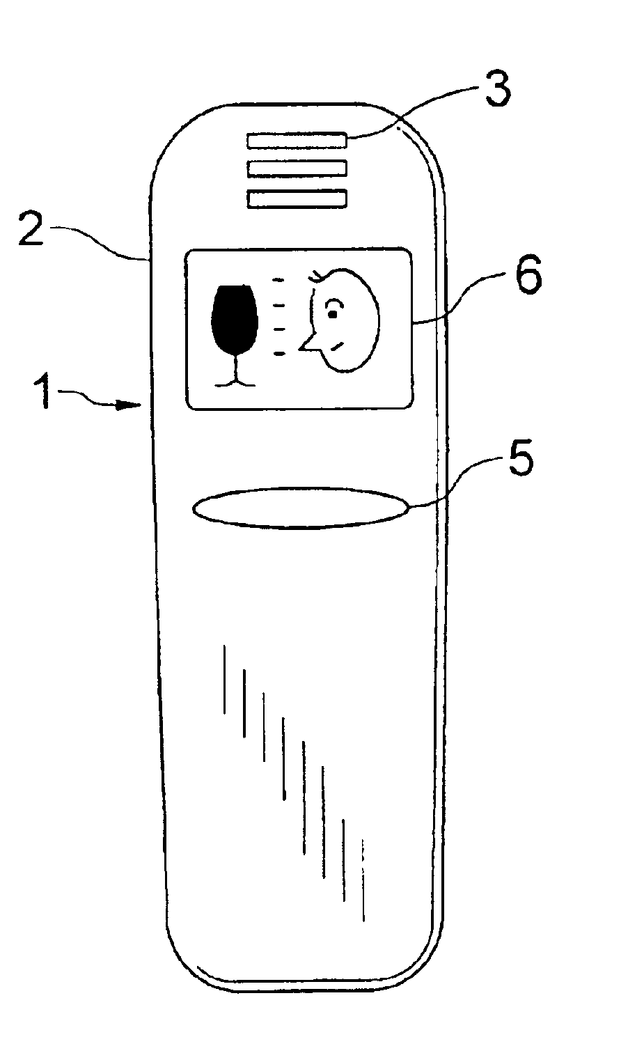
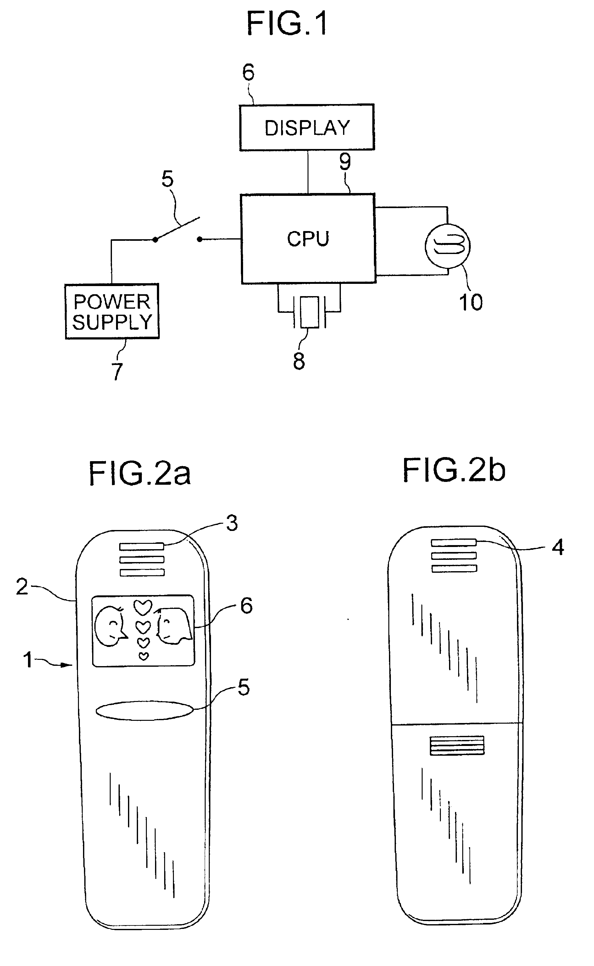
Referring to FIGS. 1 and 2, an exhalation gaseous component gauge is described as being applied to measuring the degree of unpleasant odor or bad breath. It has a palm-sized casing 2, which has exhalation taking-in and taking-out slots 3 and 4 made on its front and rear sides respectively. A display device 6 is fixed to the front side of the casing 2, and a switch 5 appears on the front side. As seen from FIG. 1, the breath gauge 1 includes, in its palm-sized casing 2, an electric power supply 7, a CPU 9 connected to the power supply 7 via the switch 5, a semiconductor gas sensor 10 connected to the CPU 9 and a buzzer 8 connected to the CPU 9. The CPU 9 can perform required arithmetic operation and control. The semiconductor gas sensor 10 is so placed as to permit the breath out of one's mouth to flow over the semiconductor gas sensor 10 on the way from the exhalation taking-in slot 3 to the exhalation taking-out slot 4. As seen from FIG. 2, the palm-sized casing 2 is so sized and c...


PUM

PropertyMeasurementUnit
concentrationaaaaaaaaaa

Abstract

Disclosed is an exhalation gaseous component gauge including, in a palm-sized casing having exhalation taking-in and taking-out slots made on its front and rear sides, a semiconductor gas sensor so placed that the air flowing from one's mouth may pass the sensor, a CPU responsive to the signal from the sensor for determining the quantity of the exhalation gaseous components, and a display for showing the so determined result. The palm-sized casing is so sized and configured as to permit one to have a look at the display while holding the gauge in hand to direct the air from the mouth to the exhalation taking-in slot. Also, disclosed is a cellular phone equipped with an exhalation gaseous component gauge.

Description

BACKGROUND OF THE INVENTION1. Field of the InventionThe present invention relates to an exhalation gaseous component gauge and a cellular phone equipped with function of measuring gaseous components, and more particularly to such a gauge and cellular phone for giving an indication of the degree of smelling bad in someone's breath or giving an indication of the degree of intoxication.2. Prior ArtsThe main cause for bad breath is the producing of volatile sulfide from bacteria plaque in mouth, where bacillus is allowed to be active at the surrounding temperature about one degree C. higher than the body temperature. The bad breath is said to be composed of hydrogen sulfide (H2S) and methyl mercaptan (CH3SH). The degree of bad smell depends on individual factors, such as age, physical condition, length of time subsequent to teeth brushing or taking foods, diseases in mouth or emission of saliva. Even though the degree of smelling bad in someone's breath is strong enough to be noticeable...

Claims


Application Information

Patent Timeline
Patent Type & Authority Patents(United States)
IPC IPC(8): G01N33/483G01N33/497H04M1/02H04M1/21H04M1/725H04M1/72H04B1/40H04M1/724
CPCG01N33/497G01N33/4972H04M1/21H04M1/0202H04M2250/12H04M1/72519H04M1/724H04B1/40
Inventor ITO, YUSUKEKOIZUMI, KUNIYOSHIKENMOCHI, HIROKI
Owner TANITA CORP
Features
  • R&D
  • Intellectual Property
  • Life Sciences
  • Materials
  • Tech Scout
  • Unparalleled Data Quality
  • Higher Quality Content
  • 60% Fewer Hallucinations
Learn More