
System to warn of an approaching emergency vehicle

a technology for emergency vehicles and warning systems, applied in television systems, instruments, transportation and packaging, etc., can solve problems such as automobile accidents, danger to all vehicles, and driver disorientation

Inactive Publication Date: 2005-02-22
BUSCEMI SALVATORE
View PDF5 Cites 27 Cited by
  • Summary
  • Abstract
  • Description
  • Claims
  • Application Information

AI Technical Summary

Benefits of technology

Yet another important objective of the invention is to provide the driver of the motor vehicle with visual indication of whether the emergency vehicle is actually approaching or is traveling away from the driver's vehicle.

Problems solved by technology

However, this basic warning system has several drawbacks and disadvantages.
At times, the driver of a motor vehicle will not hear the warning sirens, and the sudden appearance of the emergency vehicle can be disorienting to the driver.
This potential situation presents a danger to all vehicles in the vicinity, and has resulted in automobile accidents, including accidents involving the emergency vehicle itself.
As a result of these improvements in isolating the interior of passenger cars from outside noise, the danger of not hearing the siren from an approaching emergency vehicle has increased.
At other times, the driver of a motor vehicle may hear the warning sirens, but not be able to immediately detect from which direction the emergency vehicle is approaching, or whether the emergency vehicle is approaching or traveling away from the driver's vehicle.
This situation also presents the potential for danger as drivers in the vicinity are distracted, swerve to the side of the road, or slow down in an effort to locate the emergency vehicle and access the situation.

Method used


Image

  • System to warn of an approaching emergency vehicle
  • System to warn of an approaching emergency vehicle
  • System to warn of an approaching emergency vehicle

Examples


Embodiment Construction

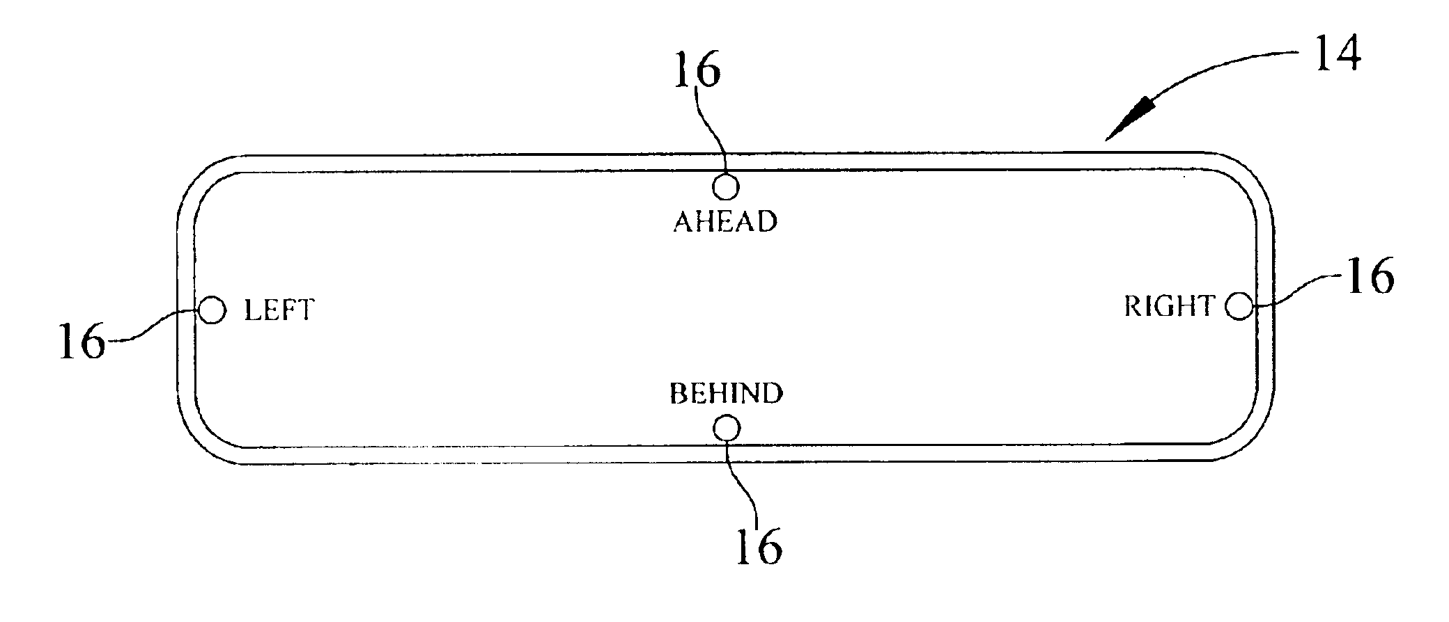
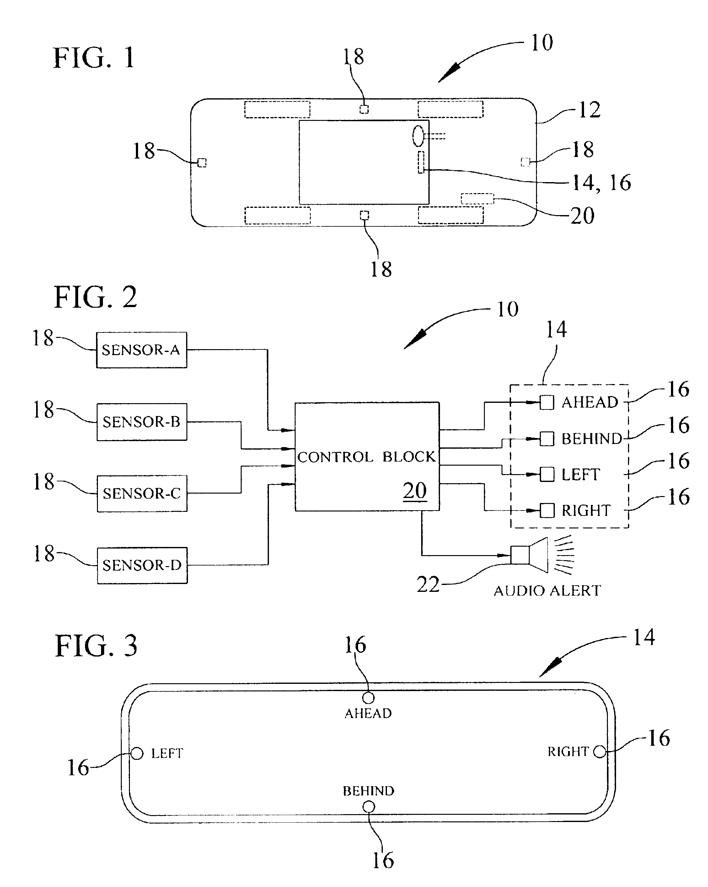
For purposes of illustration, the present invention is shown in the drawings in FIGS. 1-4 as warning system 10 for use in a motor vehicle 12. The warning system 10 is capable of providing the driver of the motor vehicle 12 with a visual notification warning of an approaching emergency vehicle (not shown), and visual indication of from which direction the emergency vehicle is approaching. As used herein, it will be understood that the phrase “emergency vehicle” includes ambulance, police, fire, and other vehicles provided with an alert-status signal generator intended to warn drivers of the presence or approach of such vehicle.

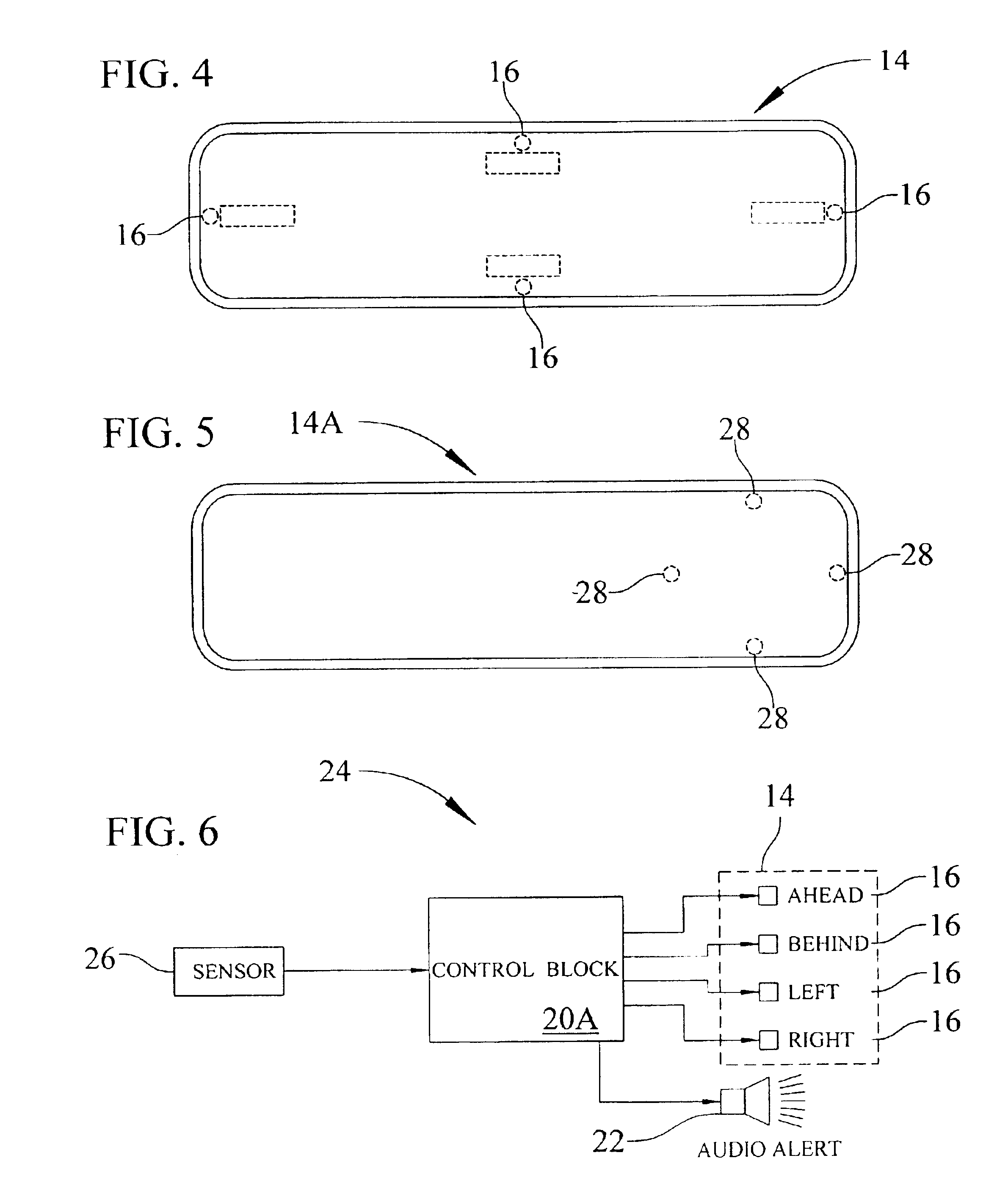
As shown in FIG. 2, the warning system 10 includes an inside rearview mirror 14 provided with emergency vehicle visual warning and directional indicative indicia 16, sensors 18 that detect the presence and approach of an emergency vehicle and provide output signals indicative thereof, and a logic control block 20 operably connected between the sensors and the v...


PUM


Abstract

A system to warn an automobile driver of an approaching emergency vehicle includes at least one sensor (18) located in the motor vehicle (12), the sensor being responsive to sense the alert-status signal from the emergency vehicle and to provide an output signal indicative thereof, a control block (20) responsive to the signal from the sensor and operative to provide an output signal indicative thereof, visual indicia (16) associated with the face of the rearview mirror (14) and receiving the output signal from the control block, and an audio alert (22) also responsive to the output signal from the control block. The visual indicia include four indicia markers located at approximately 90 degrees from one another on horizontal and vertical axes visible on the face of the mirror to provide the driver with visual directional notification of the presence and location of the emergency vehicle. The four indicia markers are normally either invisible or visually muted with respect to the face of the mirror, and are individually illuminatable responsive to the output signal from the control block. The four indicia markers establish top, bottom, left and right indicia responsive to output signals associated with the presence of an emergency vehicle located ahead, behind, to the left and to the right of the motor vehicle, respectively.

Description

BACKGROUND OF THE INVENTION1. Field of InventionThe present invention relates generally to automotive safety systems.More particularly, the invention relates to a system for warning the driver of a motor vehicle of an approaching emergency vehicle.2. Description of Related ArtTraditionally, flashing lights are relied on to notify other traffic in the immediate vicinity of the presence of an emergency vehicle in alert status, and sirens are relied on to warn the traffic ahead and to the side of an approaching emergency vehicle. This basic warning system has been used by emergency vehicles for many decades. However, this basic warning system has several drawbacks and disadvantages.At times, the driver of a motor vehicle will not hear the warning sirens, and the sudden appearance of the emergency vehicle can be disorienting to the driver. This potential situation presents a danger to all vehicles in the vicinity, and has resulted in automobile accidents, including accidents involving t...

Claims


Application Information

Patent Timeline
IPC IPC(8): G08G1/0962G08G1/0965
CPCG08G1/0965
Inventor BUSCEMI, SALVATORE
Owner BUSCEMI SALVATORE
Learn More