Method and apparatus for determining relative movement in an optical mouse using feature extraction

a technology of relative movement and optical mouse, applied in the field of optical mice, can solve the problems of many other devices that have mechanical parts, mechanical components wear out, and the cursor cannot be accurately manipulated,

Inactive Publication Date: 2005-02-22
OMNIVISION TECH INC
View PDF7 Cites 29 Cited by
  • Summary
  • Abstract
  • Description
  • Claims
  • Application Information

AI Technical Summary

Problems solved by technology

The roller ball mouse, however, has drawbacks associated with many other devices that have mechanical parts.
Namely, over time the mechanical components wear out, become dirty, or simply break down so that the cursor can no longer be accurately manipulated, if at all.
However, because the correlation calculation is performed with a single pixel shift in each direction, the maximum speed by which the optical mouse can be moved (while still providing a usable signal) is limited.
Specifically, the optical mouse cannot be moved translate more than one pixel distance between successively captured images without significant increase in the amount of correlation calculations.

Method used


Image

  • Method and apparatus for determining relative movement in an optical mouse using feature extraction
  • Method and apparatus for determining relative movement in an optical mouse using feature extraction
  • Method and apparatus for determining relative movement in an optical mouse using feature extraction

Examples


Embodiment Construction

In the following description, numerous specific details are provided, such as the identification of various system components, to provide a thorough understanding of embodiments of the invention. One skilled in the art will recognize, however, that the invention can be practiced without one or more of the specific details, or with other methods, components, materials, etc. In still other instances, well-known structures, materials, or operations are not shown or described in detail to avoid obscuring aspects of various embodiments of the invention.

Reference throughout this specification to “one embodiment” or “an embodiment” means that a particular feature, structure, or characteristic described in connection with the embodiment is included in at least one embodiment of the present invention. Thus, the appearance of the phrases “in one embodiment” or “in an embodiment” in various places throughout this specification are not necessarily all referring to the same embodiment. Furthermo...


PUM


Abstract

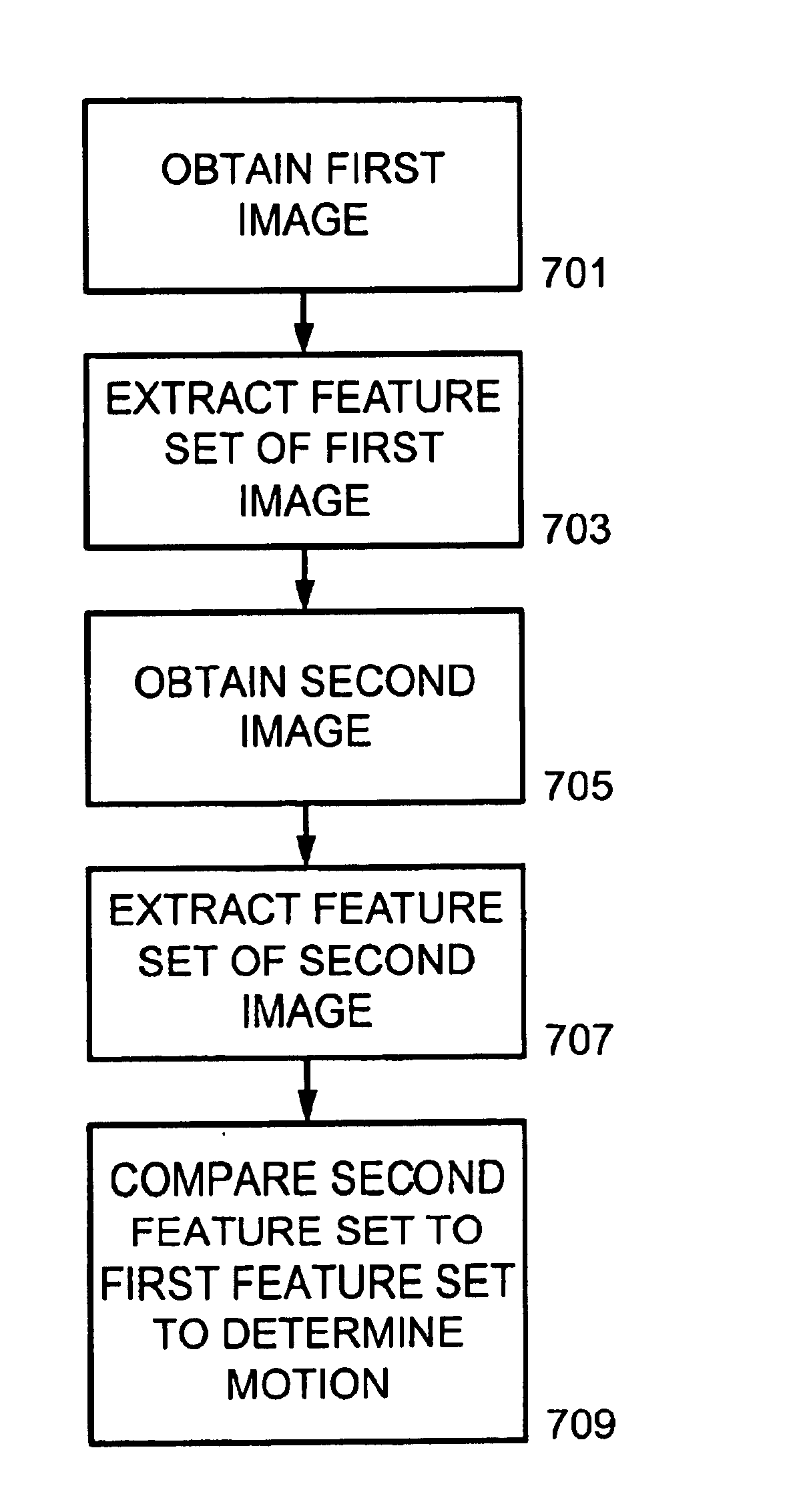
A method of determining a movement vector between two images is disclosed. The method comprises capturing a first image using a sensor array. Next, a first feature set is extracted from the first image. A second image subsequent in time from the first image is captured. Similarly, a second feature set is extracted from the second image. The first feature set is compared to the second feature set to determine a shift in position of the second image relative to the first image. Finally, the movement vector is output based upon the shift in position.

Description

TECHNICAL FIELD OF THE INVENTIONThe present invention relates generally to optical mice, and more particularly, to a method for determining movement of an optical mouse using feature extraction and with reduced calculation requirements.BACKGROUND OF THE INVENTIONVarious types of pointing devices are used as input devices that allow a user to manipulate a cursor of a computer. In laptop computers, a capacitive touch pad is commonly used to manipulate the cursor. For desktop computers, the ubiquitous computer mouse constitutes the large majority of pointing devices. The mouse allows for cursor manipulation on a visual display screen of a personal computer or workstation, for example. Cursor manipulation includes actions such as rapid relocation of a cursor from one area of the display screen to another area or selecting an object on a display screen.In a prior art “roller ball” mouse, a user controls the cursor by moving the mouse over a surface, such as a mouse pad, so that the curso...

Claims


Application Information

Patent Timeline
Patent Type & Authority Patents(United States)
IPC IPC(8): G06F3/033G06F3/03
CPCG06F3/0317
Inventor SHI, GE
Owner OMNIVISION TECH INC
Why Eureka
Try Eureka