Security classroom function lock mechanism

a function lock and classroom technology, applied in the field of high-quality cylindrical locks, can solve the problems of not allowing them to have access to the room (or any other locked room) from the outside, the inside cannot always be certain as to the locked state of the door, and the room that is securely locked before entry may become unlocked, so as to reduce the force on them

Inactive Publication Date: 2005-03-01
SARGENT MANUFACTURING CO INC
View PDF28 Cites 37 Cited by
  • Summary
  • Abstract
  • Description
  • Claims
  • Application Information

AI Technical Summary

Benefits of technology

The key driven piece includes a key end and a splined end. The splined end engages the latch mechanism when the locking piece is in the locked position. The key end and splined end are axially slidable relative to each other. A first spring biases the key end of the key driven piece away from the splined end of the key driven piece. A second spring biases the key end of the key driven piece towards the outer cylinder. The axial sliding action and spring biasing allows the independent operation of the inner and outer lock mechanisms and ensures that the outer handle is only unlocked when both mechanisms are in the unlocked state.
The latch bolt frame may be constructed as a tube enclosing the latch mechanism. The latch is sufficiently robust to prevent significant rotation of the lock core during the application of 1000 inch-pounds of torque to the lock core by the lever handle.
The locking piece is mounted in the outer sleeve so that it can slide axially from the locked position to the unlocked position. The locking piece preferably includes at least one locking lug, and more preferably, two locking lugs that project radially outward from the sleeve to engage the lock core in the locked position. This prevents the lever handle and sleeve from rotating relative to the lock core. By making the locking lugs robust and extending them outward beyond the radius of the sleeve, the forces on them are reduced and they are able to withstand significant abuse, as compared to prior art designs.
In another aspect of the present invention, endplay is eliminated from the connection of the handles to the lock. To accomplish this, the lever handle is securely mounted on the shaft portion of the sleeve to prevent axial motion of the lever handle relative to the sleeve. The sleeve includes an enlarged portion having a diameter greater than an inner diameter of the bearing receiving the sleeve. The enlarged portion of the sleeve is held in contact with a face surface of the bearing by a retaining collar. The enlarged portion of the sleeve cooperates with the face surface of the bearing to prevent axial motion of the sleeve relative to the lock core.

Problems solved by technology

This allows teachers or office workers to be issued an inside key to activate the intruder function from the inside, but does not allow them to have access to that room (or any other locked room) from the outside, if it is locked.
One problem with this type of conventional design is that the door may be switched to the unlocked condition with the outside key without the knowledge of those inside.
As a result, those inside cannot always be certain as to the locked state of the door, even after it has been locked from the inside and even though the door has never been opened.
A related problem with existing locks having this function is that opening the door from the outside with an outside key will typically unlock the door automatically.
In the confusion surrounding an intruder event, where police or security personnel may not be familiar with correct operation of the lock, rooms that are securely locked before entry may become unlocked.
This problem is particularly acute for cylindrical locks, which have less internal room than mortise type locks to accommodate heavy-duty locking components.
Another problem relates to the unbalanced shape of a lever handle, which tends to cause the lever handle to droop.
A lever handle, however, requires much more force to return it to the level position.
Sufficient force cannot be provided by the latch rod return springs, so most lever handle designs incorporate auxiliary lever handle return springs.
While this is effective, locating the lever handle return springs in the rose produces a thick rose that is considered by some to be relatively unattractive.
However, if a lever handle does not fully return to the level rest position, it appears to droop.
Such visual droop is particularly objectionable.
However, heretofore it has been difficult to arrange for the lever handle to return to a position above level without constructing the lock in two different versions for left-hand swing and right-hand swing doors or without placing the stops in the rose.
If the stop position were to be located in the lock mechanism, however, this rotation about a horizontal axis would cause the above-level stop position to reverse to an objectionable below-level position.
Requiring separate locks for left and right-hand swing doors, however, is undesirable as it increases inventory costs and results in confusion and delay when the wrong lock is ordered.
Placing the stops in the rose, however, is undesirable, as it requires that the rose be made thick to accommodate the stops.
Such a large diameter rose is considered by some to be unattractive and the large diameter increases the cost of the rose.
Another problem with prior art lever handle cylindrical locks arises as a result of the method used to attach the handle to the lock mechanism.
This motion is perceived as a “loose” handle by the user and is undesirable.
Often, there is also some relative motion between the shaft and the lock mechanism as well, which contributes additional objectionable axial motion between the handle and the door.

Method used


Image

  • Security classroom function lock mechanism
  • Security classroom function lock mechanism
  • Security classroom function lock mechanism

Examples


Embodiment Construction

)

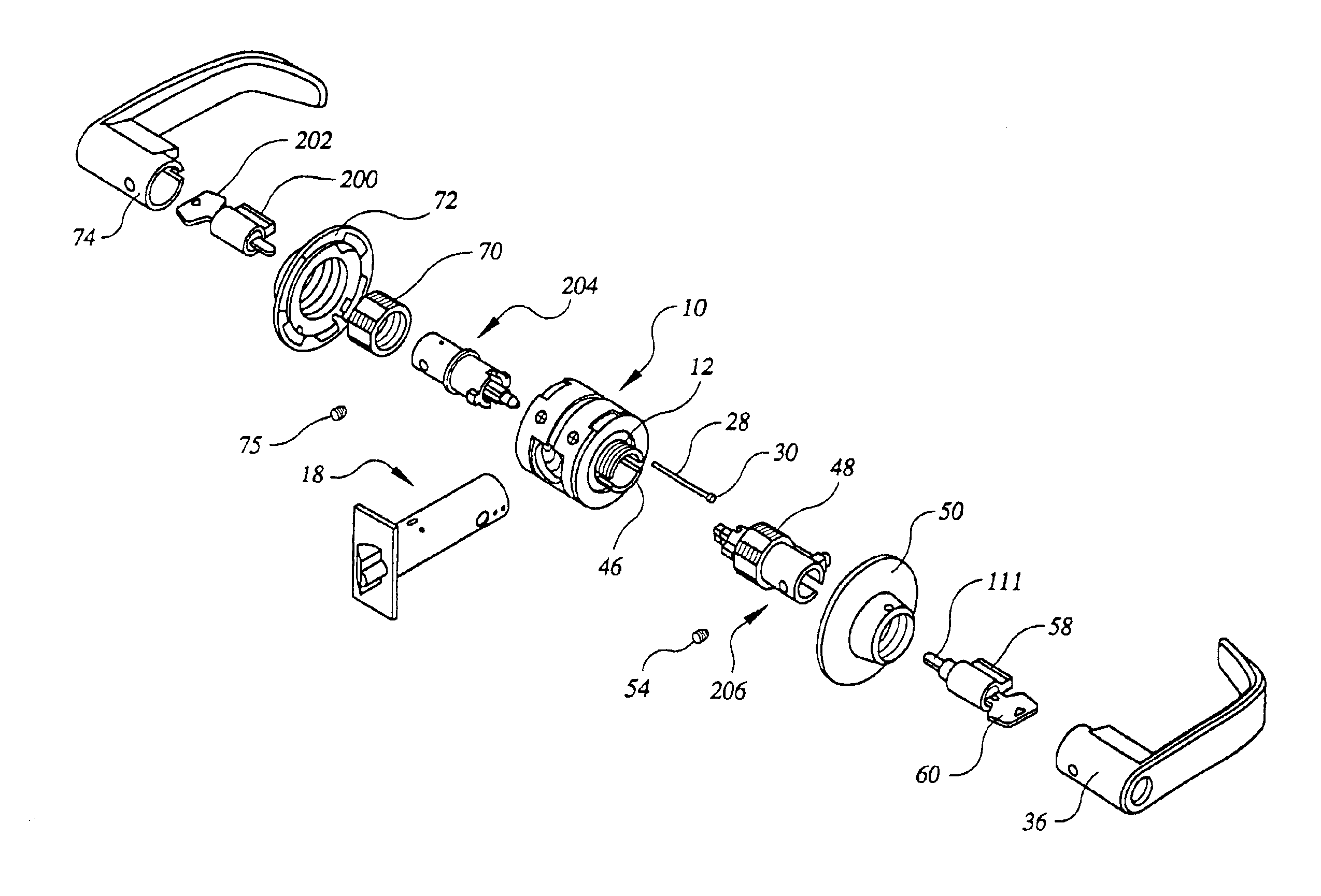
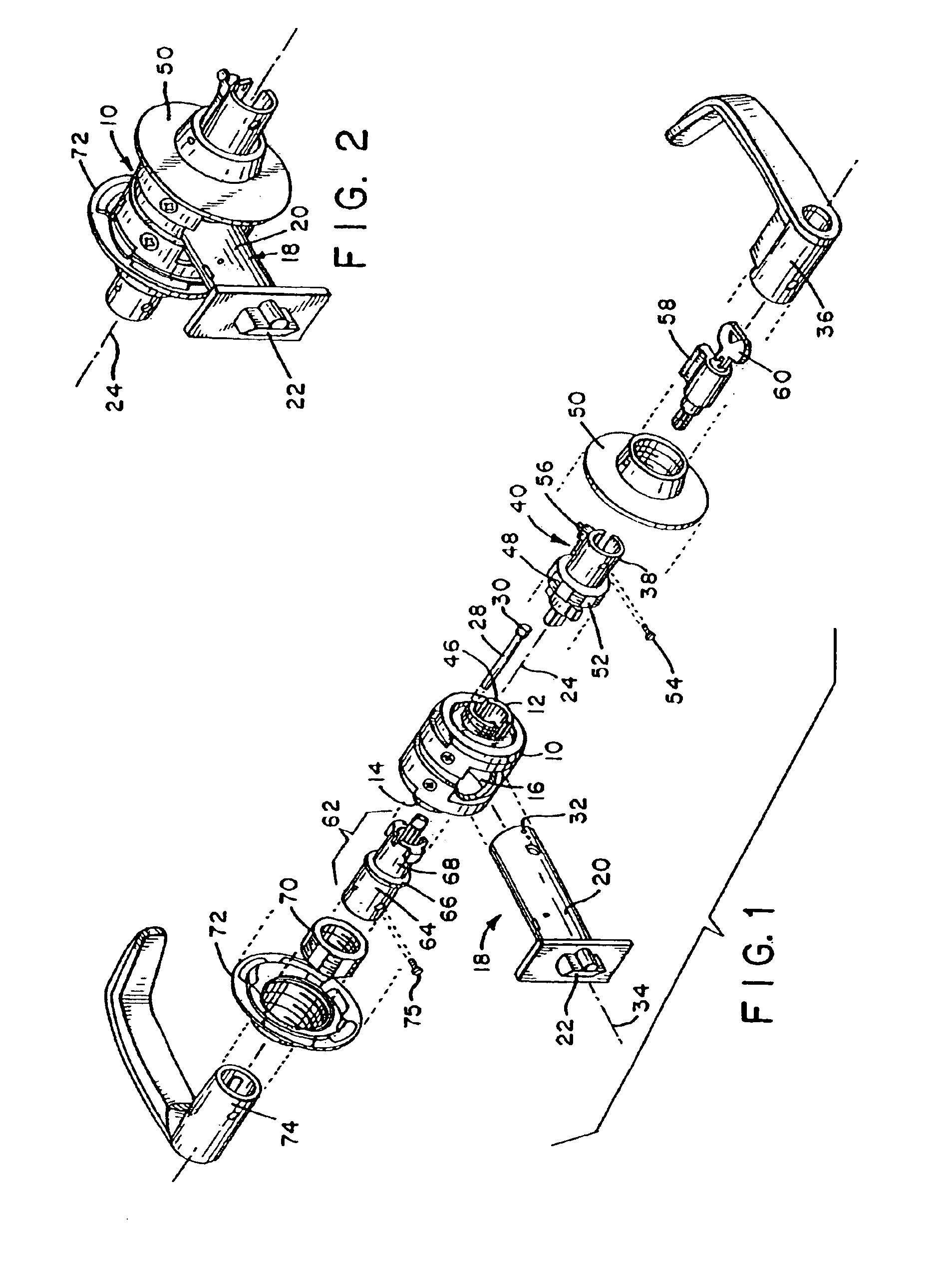
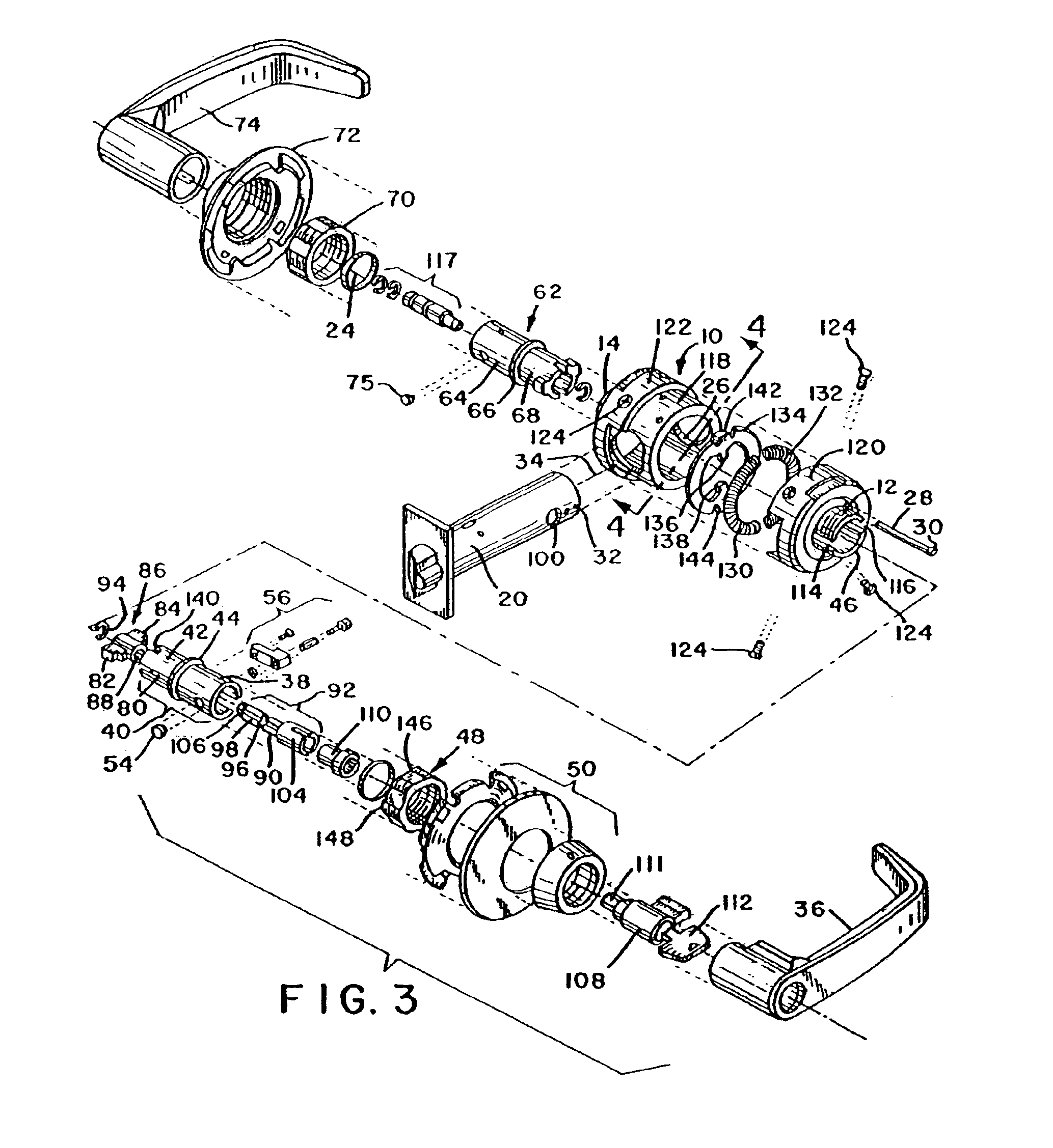
In describing the preferred embodiment of the present invention, reference will be made herein to FIGS. 1-10 of the drawings in which like numerals refer to like features of the invention. The embodiment of the lock shown in FIGS. 1-7, which does not include the security classroom lock mechanism, will be described first to provide a basis for better understanding the operation of the lock when equipped with the security classroom lock mechanism.

Referring to FIGS. 1 and 2, the present invention includes a lock core 10 having two externally threaded bearings 12, 14 on opposite sides. The lock core 10 includes a front opening 16 that receives a latch mechanism 18 including a latch bolt frame 20 formed in the shape of a tube. The latch mechanism 18 includes a latch bolt 22 and a retractor mechanism 102 (see FIGS. 6 and 7) located within the latch bolt frame 20 for retracting the latch bolt.

The tube comprising the latch bolt frame 20 extends through opening 16 in the front of the lock c...


PUM


Abstract

A lock mechanism operated by inner and outer lever handles provides a security classroom function and includes inner and outer lock mechanisms that are independently switchable between locked and unlocked states by inner and outer lock cylinders and keys. The inner handle always operates the lock mechanism to retract a latch bolt. The outer handle can only retract the latch bolt when both the inner and outer lock mechanisms are in the unlocked state. The outer key can retract the latch bolt when the inner lock mechanism is in the locked state, but cannot change the inner lock mechanism to the unlocked state or enable the outer handle, thereby ensuring positive control over the locked state of the outer handle from the inner side.

Description

BACKGROUND OF THE INVENTION1. Field of the InventionThe present invention relates to high quality cylindrical locks provided with an intruder or security classroom function in which the lock mechanism can be locked with a key from the inside to prevent entry by an intruder into an occupied classroom or office. The invention is particularly useful in lever handle designs, often required in public buildings, where an intruder could apply a very high level of torque to the locking mechanism through the lever handle.2. Description of Related ArtLocks used in commercial and public buildings, such as office buildings and schools, are increasingly being provided with a security classroom function (also referred to as an “intruder” function). This type of lock is typically used on inner doors to separate classrooms or offices from hallways or public areas.Locks with this function have key operated lock cylinders on both sides of the door. Turning the key on either side of the door will lock...

Claims


Application Information

Patent Timeline
Patent Type & Authority Patents(United States)
IPC IPC(8): E05B55/00E05B1/00E05B55/14E05B17/00E05B63/10E05B63/14E05B63/16
CPCE05B9/08E05B13/108E05B55/005E05B63/10E05B63/08Y10T70/5832Y10T70/5442Y10T70/5394Y10T70/577Y10T70/5801E05B13/10
Inventor ELLER, DARREN C.SORENSON, DAVID A.ZIMMER, TODD C.
Owner SARGENT MANUFACTURING CO INC
Why Eureka
Try Eureka