Weight detector for elevator

a detection apparatus and weight technology, applied in the direction of instruments, elevators, force/torque/work measurement apparatus, etc., can solve the problem of long time-consuming and laborious detection operation, and achieve the effect of saving or reducing installation space and maintaining stability in detection operation

Inactive Publication Date: 2005-03-01
MITSUBISHI ELECTRIC CORP
View PDF18 Cites 10 Cited by
  • Summary
  • Abstract
  • Description
  • Claims
  • Application Information

AI Technical Summary

Benefits of technology

The present invention is intended to obviate the problem as referred to above, and has for its object to provide a load detection apparatus for an elevator which is capable of saving or reducing the installation space and maintaining stability in its detection operation for an extended period of time.
In addition, the load detection apparatus for an elevator is characterized in that in order to generate a frictional force between the wire and the pulley so as to prevent slippage of the wire, a spring is connected with that end of the wire which is opposite to its end near the shackle for pulling the wire in a direction toward the pulley.
Moreover, the load detection apparatus for an elevator is characterized in that in order to generate a frictional force between the wire and the pulley so as to prevent slippage of the wire, a weight is hung from that end of the wire which is opposite to its end near the shackle for pulling the wire in a direction toward the pulley.

Problems solved by technology

With the conventional apparatus as constructed above, since a space for installation of each differential transformer is required and each differential transformer acting as a sensor has sliding portions, the detection operation is not stabilized for a long period of time, and it is necessary to frequently conduct tests or inspections.

Method used


Image

  • Weight detector for elevator
  • Weight detector for elevator
  • Weight detector for elevator

Examples


embodiment 1

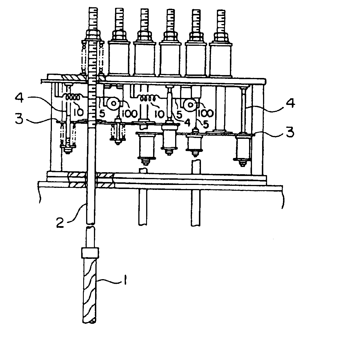
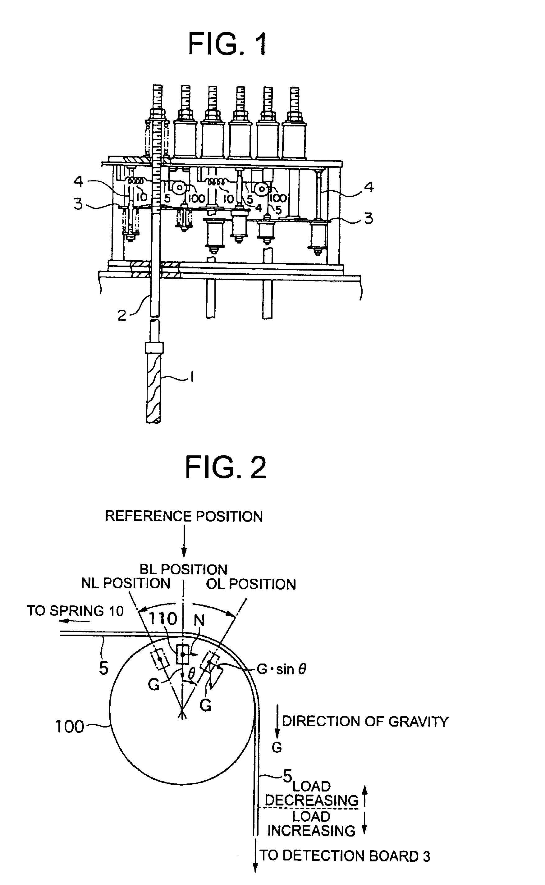
FIG. 1 is a view which shows the construction of a load detection apparatus for an elevator according to a first embodiment of the present invention. In this figure, 1 designates main ropes, 2 shackles, 3 detection boards which are coupled with the corresponding shackles 2, respectively, and each of which has a surface arranged perpendicular to a corresponding shackle and capable of being displaced together therewith, 4 studs, 5 wires, 10 springs, 100 pulleys on each of which an acceleration sensor to be described later is installed. The parts same as or corresponding to those of the prior art are identified by the same symbols.

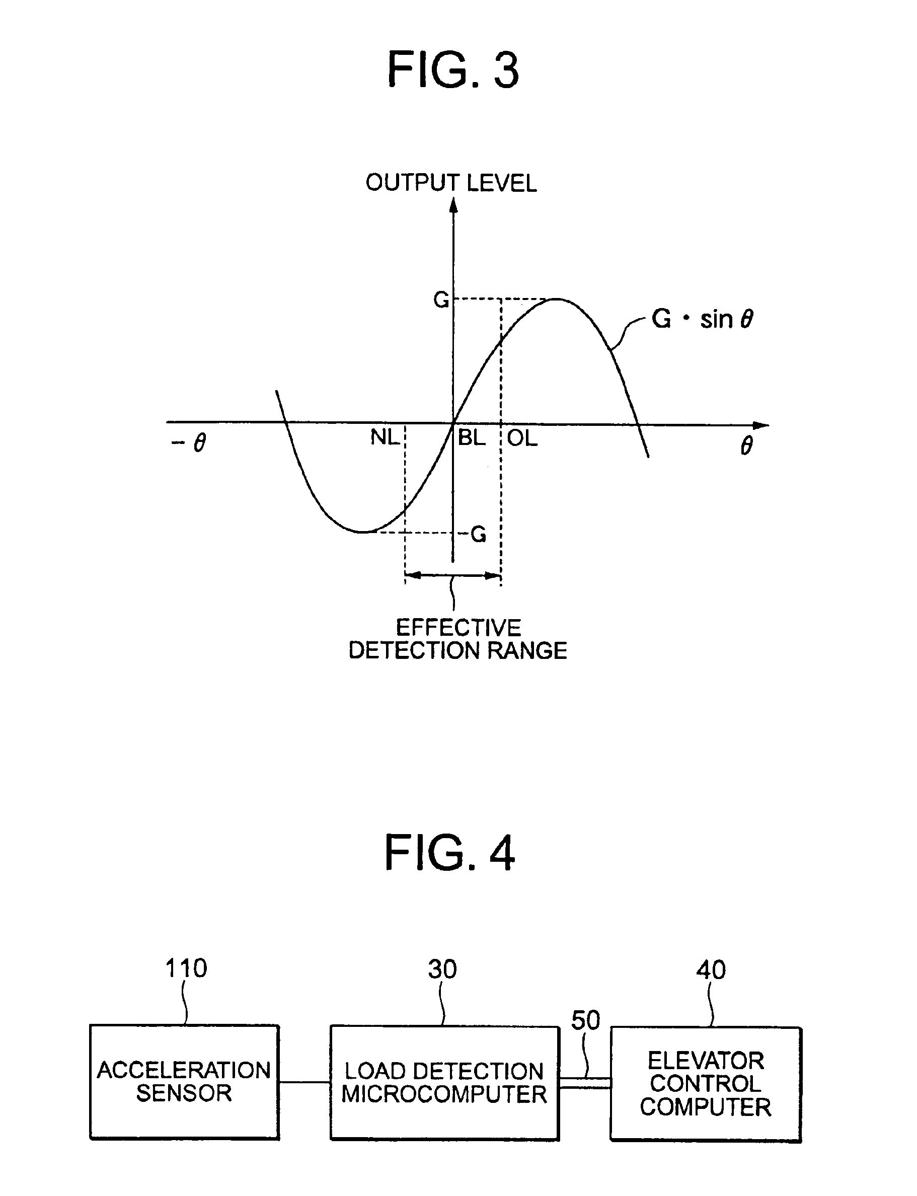
In the present invention, when a detection board 3 engaged with a shackle 2 is displaced in accordance with a variation in the loading capacity of a car associated therewith, a corresponding wire 5 is caused to accordingly move thereby to rotate a corresponding pulley 100, whereby the load of the car is detected by determining the rotational position of that ...

embodiment 2

In addition, in cases where a semiconductor acceleration sensor is used as the above-mentioned acceleration sensor, there might be developed an output error (hereinafter referred to as a temperature drift) due to the influence of the ambient temperature. In particular, elevators can be used in severe environments with large temperature changes, and hence it is necessary to give enough consideration to the influences caused by a change in temperature of the acceleration sensor. Thus, in this embodiment, such a temperature drift can be suppressed by keeping the semiconductor acceleration sensor at a constant temperature.

FIG. 6 is a view which shows the construction in surroundings of the semiconductor acceleration sensor used with a load detection apparatus for an elevator according to this embodiment. In FIG. 6, 110a designates a semiconductor acceleration sensor which constitutes the acceleration sensor as explained in the above-mentioned first embodiment, and 61 designates a printe...


PUM

PropertyMeasurementUnit
rotational angleaaaaaaaaaa
angleaaaaaaaaaa

Abstract

The displacement of a shackle, which is coupled with a main rope hanging an elevator car, caused by loading of the car, is converted, through a wire, into the rotary motion of a pulley which has a substantially vertical rotating surface, and an acceleration sensor for detecting the angle of rotation of the pulley is fixedly secured to the pulley, so that the load of the car is detected from the angle of rotation of the pulley.

Description

TECHNICAL FIELDThe present invention relates to a load detection apparatus for an elevator capable of detecting the loading capacity of an elevator car.BACKGROUND ARTA conventional load detection apparatus for an elevator described in Japanese Patent Application Laid-Open No. 7-101646 is shown in FIG. 9. In this figure, 1 designates main ropes (or ropes), 2 shackles, 3 detection boards, 4 studs, 5 wires, 6 pulleys, and 7 differential transformers.This load detection apparatus for an elevator is installed in a machine room arranged on the top of a vertical passage for an elevator car. When the plurality of shackles 2, with which end portions of the main ropes 1 for hanging the elevator car are connected, are caused to move under the action of the load of the car, the detection boards 3 are displaced in accordance with the movements of the shackles 2 while being guided by the studs 4, whereby the loading capacity of the car is detected based on the displaced positions of the detection...

Claims


Application Information

Patent Timeline
Patent Type & Authority Patents(United States)
IPC IPC(8): B66B1/34B66B5/14G01G19/00G01G19/14B66B1/44B66B3/00
CPCB66B1/3484G01G19/14B66B5/14
Inventor YAMAKAWA, SHIGEKIHORIZAKI, KAZUHIRO
Owner MITSUBISHI ELECTRIC CORP
Why Eureka
Try Eureka