Method and device for limiting the starting current and for discharging the DC voltage intermediate circuit

a technology of dc voltage intermediate circuit and starting current, which is applied in the direction of secondary cell servicing/maintenance, capacitor propulsion, hybrid vehicles, etc., can solve the problems of dangerous leakage current, and achieve the effects of simple and cost-effective means, safe, saving or reducing installation spa

Active Publication Date: 2014-05-20
ROBERT BOSCH GMBH
View PDF9 Cites 14 Cited by
  • Summary
  • Abstract
  • Description
  • Claims
  • Application Information

AI Technical Summary

Benefits of technology

[0004]It is an object of the present invention, using simple and cost-effective means, to make possible the safe and rapid discharging of all capacitors in the DC voltage intermediate circuit, while simultaneously saving or reducing installation space.
[0005]An advantage of an example embodiment of the present invention is that, in the case of the methods according to the present invention and the associated devices for discharging all capacitors that are connected to the DC voltage intermediate circuit, the precharging resistor, that is already present, and that is normally in the battery, is used. Since the precharging resistor is already present, an additional discharge circuit is not needed or may be clearly reduced in the dimensioning.
[0006]An additional advantage is that the precharging resistor is usually dimensioned in such a way that a discharge is possible in a very short discharge time, usually clearly more rapidly than by using a separate discharge circuit.
[0008]A further advantage of the example embodiment of the present invention is that it ensures the generally required very great vehicle availability. This means that, during the start of the hybrid vehicle, no time delays noticeable to the driver occur because of the charging of the intermediate circuit capacitors. Therefore, the precharging resistors should be dimensioned to be sufficiently big, so that a charging process of the intermediate circuit capacitors is normally completed in ca. 100 ms.
[0010]The particular advantage of the example embodiment of the present invention is the simultaneous utilization of the precharging resistors for the charging and discharging process of the intermediate circuit. To achieve a discharge time of the same order of magnitude as is to be implemented using the precharging resistors, one would have to use an additional, separate resistor in the design approaches known from the related art, and therefore the design approach of the present invention has a competitive advantage at a simultaneous reduction in costs.

Problems solved by technology

These voltages are designated as being high voltage in the vehicle, and they are the cause of dangerous leakage currents.

Method used


Image

  • Method and device for limiting the starting current and for discharging the DC voltage intermediate circuit
  • Method and device for limiting the starting current and for discharging the DC voltage intermediate circuit
  • Method and device for limiting the starting current and for discharging the DC voltage intermediate circuit

Examples


Embodiment Construction

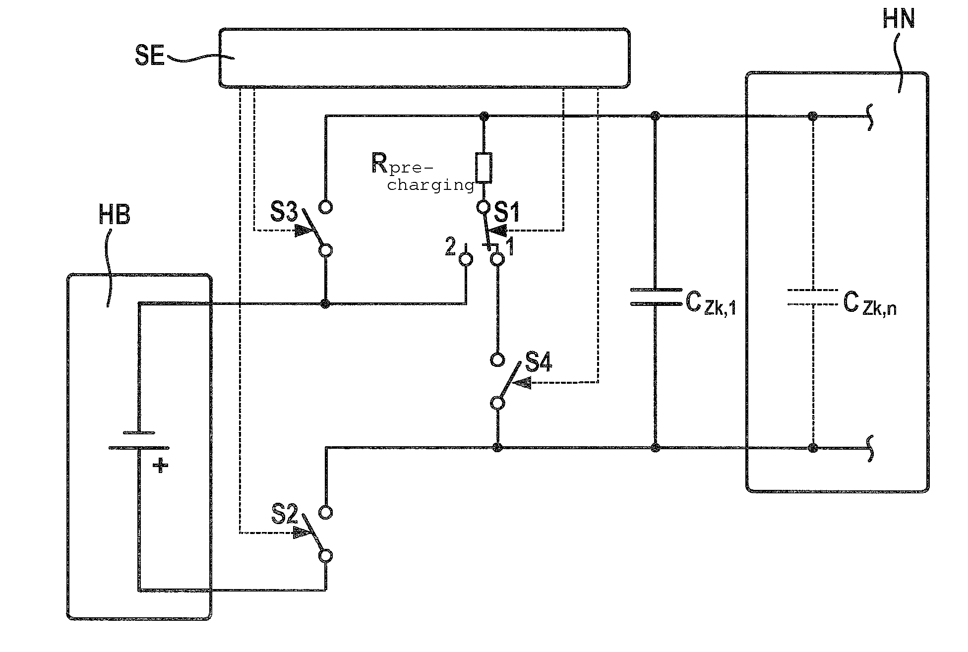
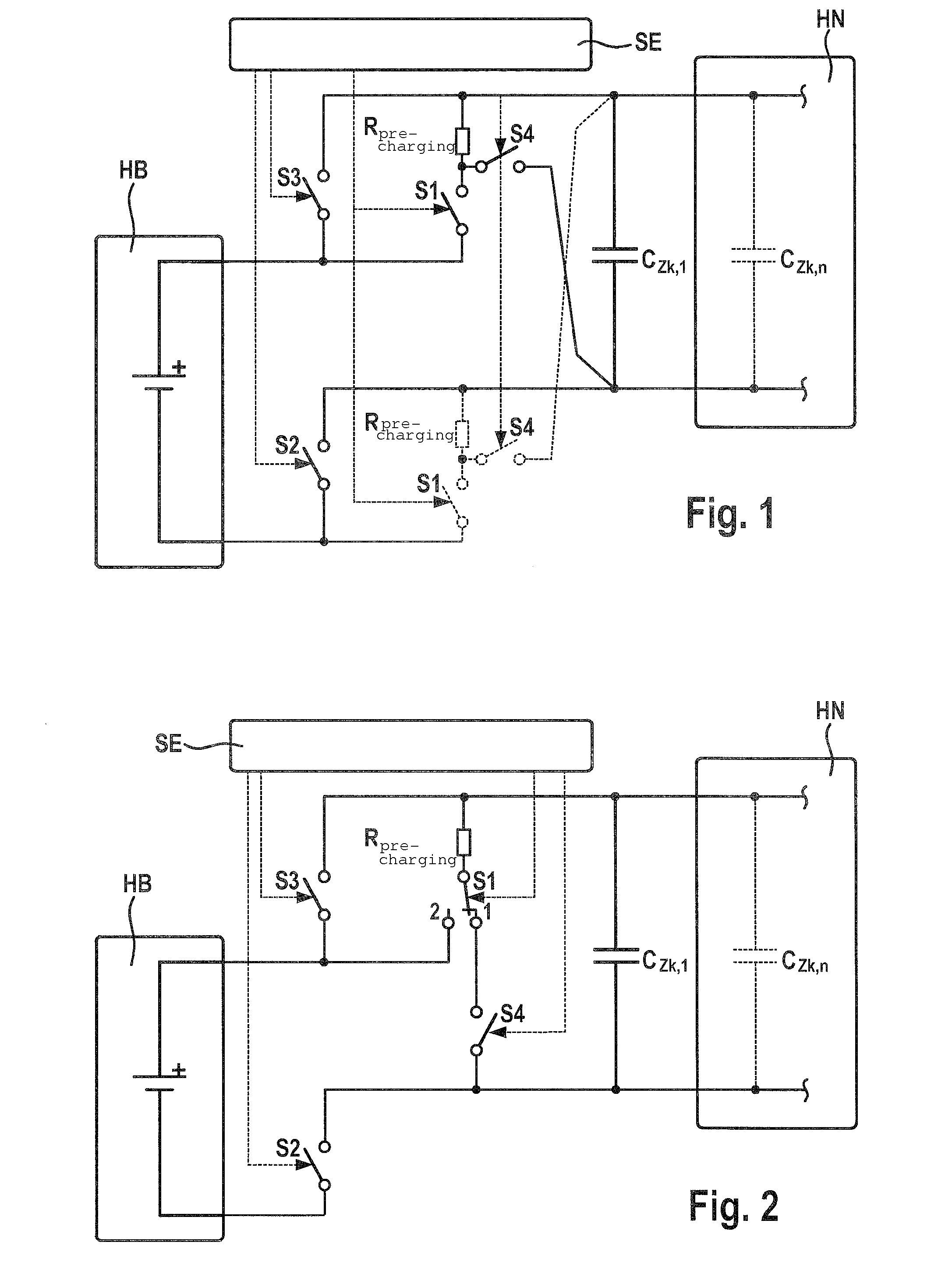
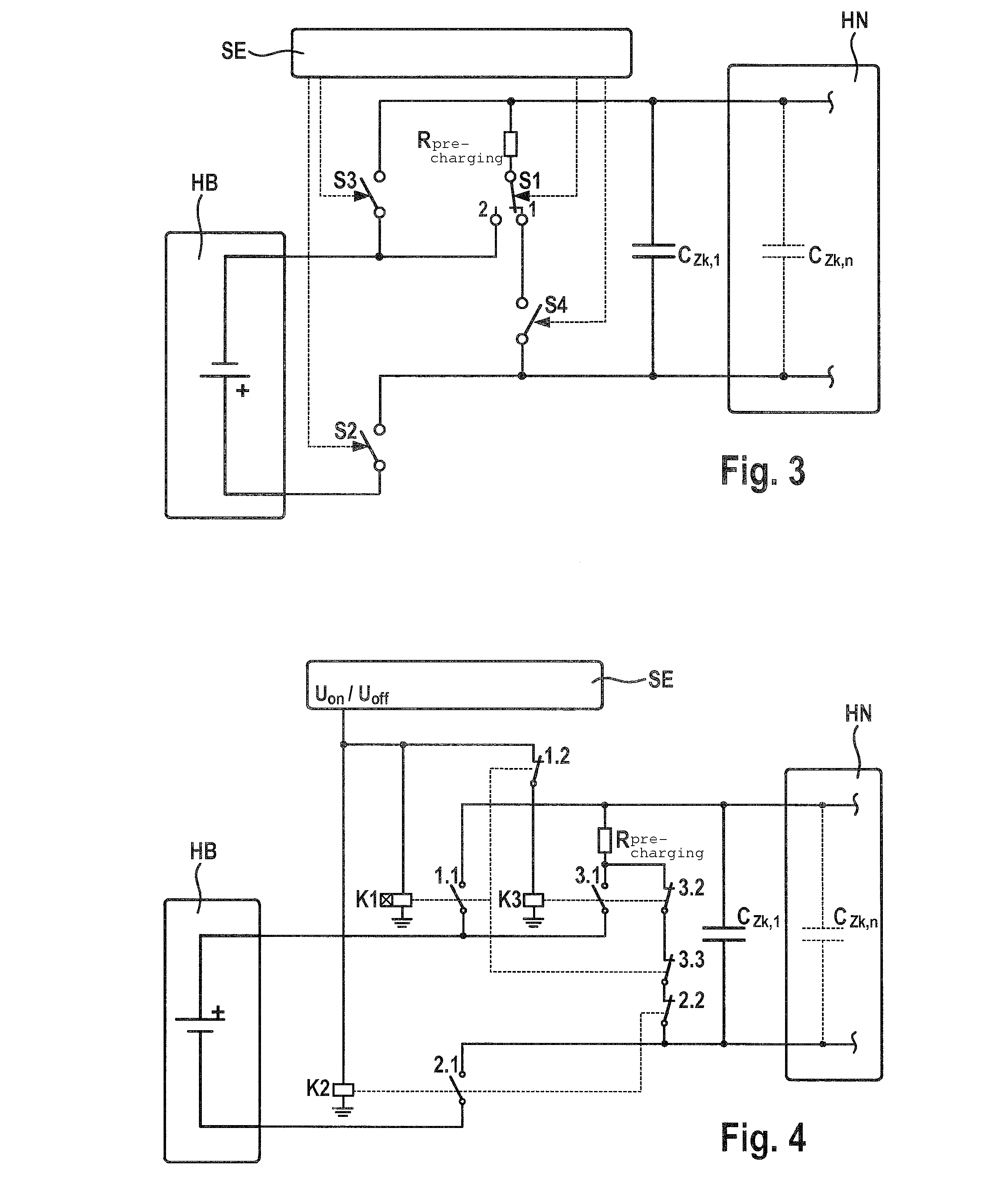
[0019]In the exemplary embodiments according to FIGS. 4 and 5, the following graphic symbols are used for the intermediate circuit discharge, but in the remaining exemplary embodiments, only make contact elements S1 to S4 of the switching devices are given.

[0020]

[0021]Switching device, for instance, main relay, main contactor having pickup delay; the pickup delay time usually corresponds to the time required for precharging all capacitors in the DC voltage intermediate circuit.

[0022]

[0023]Switching device, e.g. main relay, main contactor.

[0024]

[0025]Switching device, e.g. precharging relay, precharging contactor.

[0026]

[0027]Precharging resistor; usual dimensioning Rprecharging 30-50Ω, 200W.

[0028]

[0029]Break contact of a switching device (relay, contactor).

[0030]

[0031]Make contact of a switching device (relay, contactor).

[0032]

[0033]Chassis ground.

[0034]FIG. 1 shows the principle of the charging and discharging process with the aid of a circuit and device according to an example embo...


PUM


Abstract

Methods and associated devices are described for discharging the high-voltage network, particularly a DC voltage intermediate circuit, in which for discharging the capacitors of the high-voltage network, switching devices are used that lie between the capacitors and at least one precharging resistor and a high-voltage battery, and the switching devices are switches having a specifiable positioning of the switching contacts or switching units or relays or contactors, which are switchable with the aid of a control device. The operation of the switching units takes place in such a way that the at least one precharging resistor is used simultaneously for charging and discharging the DC voltage intermediate circuit.

Description

FIELD OF THE INVENTION[0001]The present invention relates to a method and devices for discharging the high-voltage network, especially in a hybrid vehicle or an electric highway vehicle.BACKGROUND INFORMATION[0002]In a hybrid vehicle and an electric highway vehicle voltages are used that are greater than 60 V DC. These voltages are designated as being high voltage in the vehicle, and they are the cause of dangerous leakage currents. The high voltage network, also called DC voltage intermediate circuit, in a hybrid vehicle and an electric highway vehicle, in the simplest case is made up of a battery, a voltage inverter having a DC voltage intermediate circuit capacitor, and one or more electric machines, additional high voltage consumers such as an electric climate control compressor and a cable harness which connects all the high voltage components to one another. The voltage inverter requires a DC voltage intermediate circuit capacitor for its functioning, having a sufficiently gre...

Claims


Application Information

Patent Timeline
Patent Type & Authority Patents(United States)
IPC IPC(8): H02J7/00
CPCY02T90/34B60L11/1803B60L3/0053Y02T10/7022H02M1/36B60L3/0092B60L3/04Y02T10/7005B60L3/0007B60L11/005B60L3/0046B60L50/40B60L50/51H02M1/322Y02T10/70Y02T90/40
Inventor DITTMER, BERNDWINTER, ARNOLDMIKULEC, DRAGAN
Owner ROBERT BOSCH GMBH
Why Eureka
Try Eureka