Method for operating an internal combustion engine and device for carrying out the method

a technology of internal combustion engine and internal combustion engine, which is applied in the direction of engines, machines/engines, mechanical equipment, etc., can solve the problems of increased nox current and other problems, and achieve the effects of reducing administration costs, reducing reagent substance slippage, and optimal reagent substance metering

Inactive Publication Date: 2011-09-27
ROBERT BOSCH GMBH
View PDF14 Cites 9 Cited by
  • Summary
  • Abstract
  • Description
  • Claims
  • Application Information

AI Technical Summary

Benefits of technology

[0012]An important advantage of the procedural approach according to the invention results from a reduced administrational outlay. The procedural approach according to the invention particularly achieves a metering of the reagent substance, which has only a slight overshooting and undershooting of the desired quantity. An optimal metering of the reagent substance is thereby achieved; so that on the one hand a minimal reagent substance slip can be assured, and on the other hand a large NOx conversion can be assured.
[0013]The procedural approach according to the invention can thus be implemented with simple and cost effective means so that merely a NOx sensor disposed downstream after the SCR catalytic converter is required, which has an inherently undesirable lateral sensitivity to the reagent substance. This lateral sensitivity is specifically utilized in the procedural approach according to the invention.

Problems solved by technology

Due to the lateral sensibility of the NOx sensor to the reagent substance, a decision cannot be made offhand when a detected difference occurs, if an overdosage of the reagent substance exists, which leads to a reagent substance slip; or if an underdosage of the reagent substance exists, which gives occasion to an increased NOx current.

Method used


Image

  • Method for operating an internal combustion engine and device for carrying out the method
  • Method for operating an internal combustion engine and device for carrying out the method

Examples


Embodiment Construction

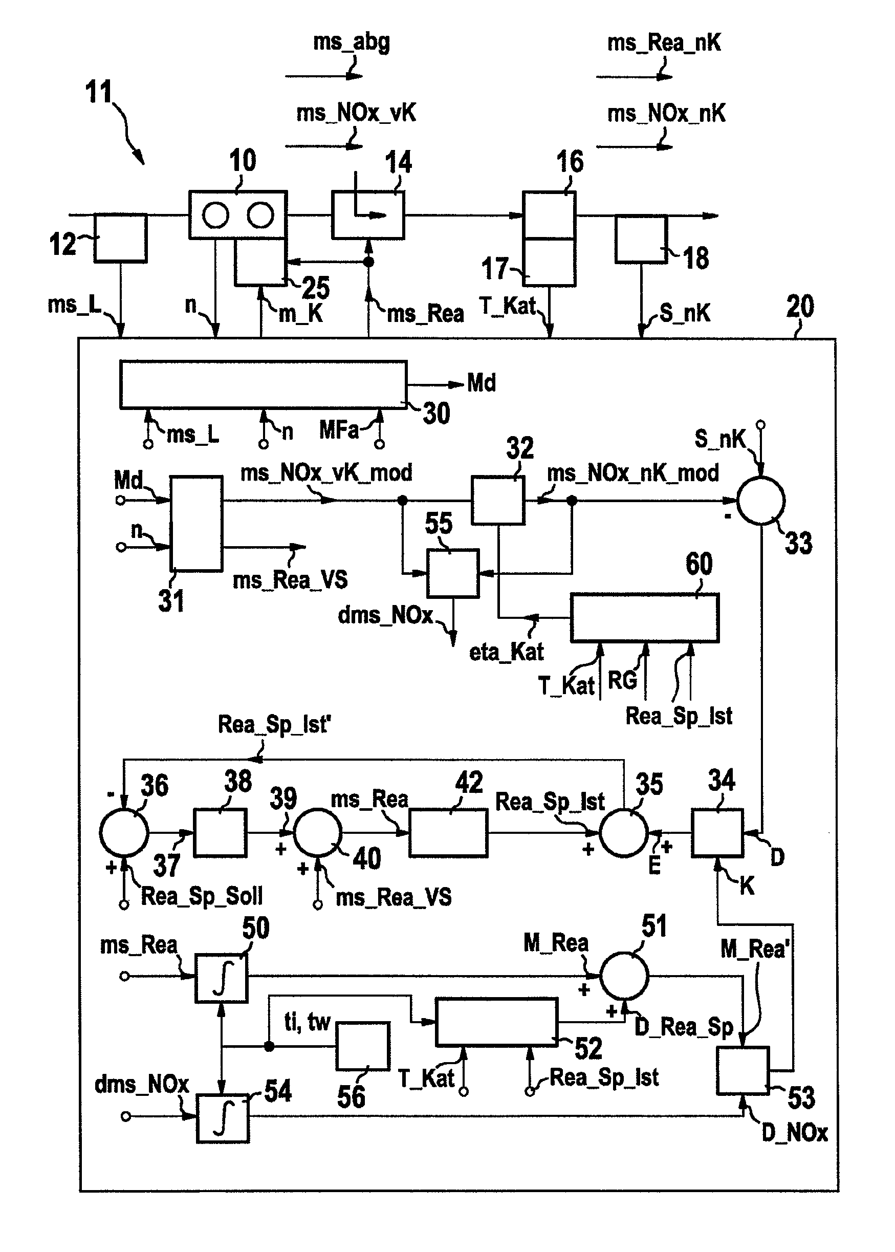
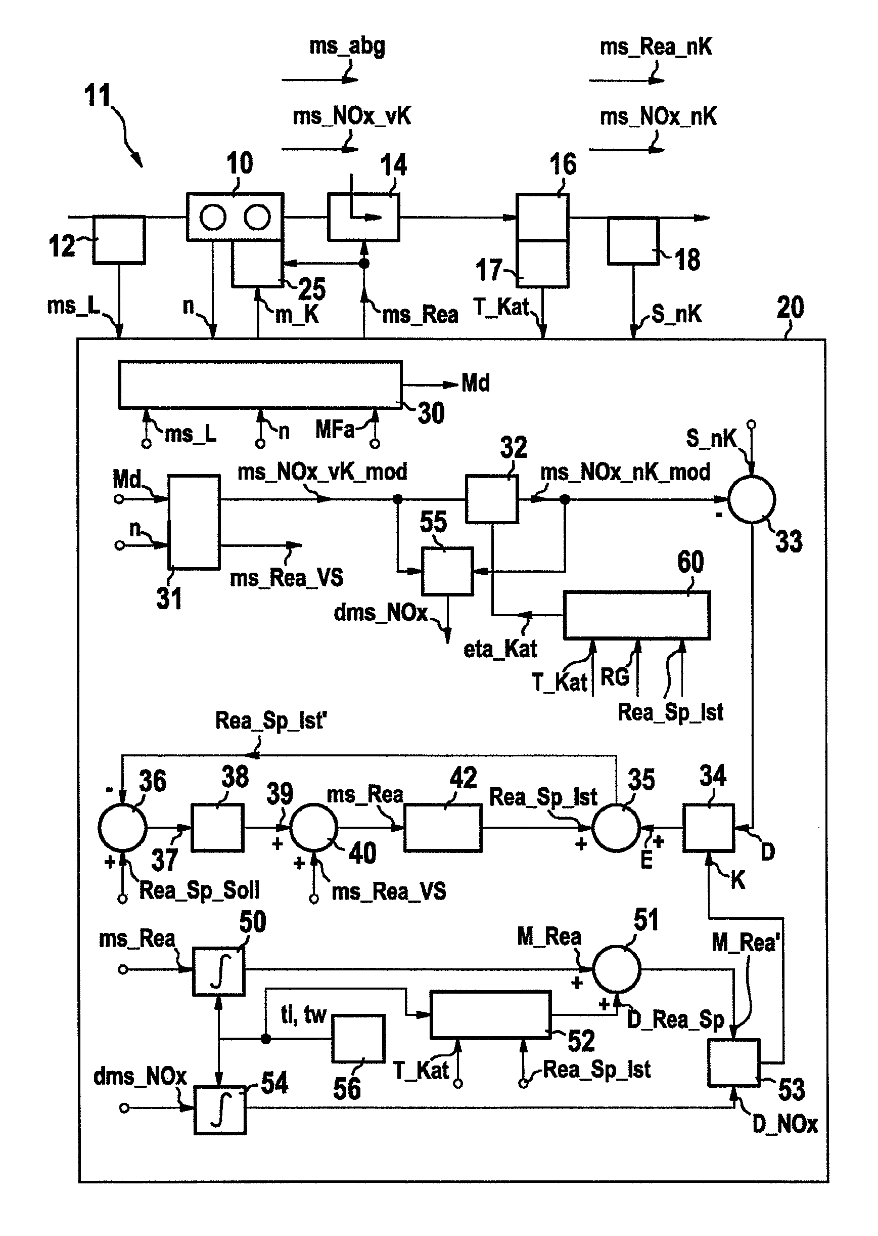
[0023]The FIGURE shows an internal combustion engine 10, in whose air intake section 11, an air ascertainment 12 is disposed; and in whose exhaust gas region 13, a reagent substance metering 14, a SCR catalytic converter 16, a temperature sensor 17 assigned to the SCR catalytic converter 16 as well as a NOx sensor 18, which is disposed downstream after the SCR catalytic converter 16, are disposed.

[0024]An exhaust gas current ms_abg as well as an untreated NOx current before the SCR catalytic converter ms_NOx_vK arises downstream after the internal combustion engine 10. A NOx current ms_NOx_nK as well as a reagent substance slip ms_Rea_nK arises downstream after the SCR catalytic converter 16.

[0025]The air ascertainment 12 provides an air signal ms_L to a control unit 20; the internal combustion engine 10 provides an engine rotational speed signal n; the temperature sensor 17 provides a measure for the temperature te_Kat of the SCR catalytic converter 16; and the NOx sensor 18 makes ...


PUM


Abstract

A method for operating an internal combustion engine in whose exhaust gas region at least one SCR catalytic converter is arranged, a reagent which contributes to NOx conversion in the SCR catalytic converter being applied to said SCR catalytic converter, and a device for carrying out the method are proposed. A measure for the NOx current which occurs downstream of the SCR catalytic converter is both calculated and measured with an NOx sensor which has lateral sensitivity to the reagent. The difference between the calculated measure and the measured measure of the NOx current is determined. A reagent signal which defines the metering of the reagent is influenced as a function of the difference. Plausibility checking is provided, during which the reagent quantity which is metered in a predefined time period and the reagent quantity which is converted in the SCR catalytic converter and / or the converted NOx quantity are compared with one another. When a deviation is detected, a correction signal which also influences the reagent signal is made available.

Description

TECHNICAL FIELD[0001]The invention proceeds from a procedure to operate an internal combustion engine, in whose exhaust gas region, a NOx sensor, which has lateral sensitivity to the reagent substance, which contributes to the NOx conversion in the SCR catalytic converter, is disposed downstream after the SCR catalytic converter; and from a device to implement the procedure according to the class of the independent claims.BACKGROUND[0002]In the German patent DE 199 03 439 A1 a procedure and a device to operate an internal combustion engine are described, in whose exhaust gas region a SCR catalytic converter (Selective Catalytic Reduction) is disposed, which reduces the nitrogen oxides contained in the exhaust gas of the internal combustion engine to nitrogen using a reagent substance. The metering of the reagent substance is carried out preferably as a function of the operating parameters of the internal combustion engine, such as, for example, the engine rotational speed and the am...

Claims


Application Information

Patent Timeline
Patent Type & Authority Patents(United States)
IPC IPC(8): F01N3/00F01N3/10
CPCF01N3/208F01N2560/026F01N2560/06F01N2610/02F01N2610/146F01N2900/0402F01N2900/08F01N2900/14F01N2900/1814Y02T10/24Y02T10/12
Inventor WALZ, CHRISTIANLOEHR, MATTHIASRUDOLPH, ANDREAS
Owner ROBERT BOSCH GMBH
Why Eureka
Try Eureka