Method for operating an exhaust gas system of an internal combustion engine

a technology of exhaust gas system and internal combustion engine, which is applied in the direction of machines/engines, analogue processes for specific applications, instruments, etc., can solve the problems of difficult estimation or ascertainment, impaired nitrogen oxide reduction in scr catalyst, etc., and achieve the effect of reducing nitrogen oxides and nox reduction capability of aqueous urea solution

Inactive Publication Date: 2013-06-06
ROBERT BOSCH GMBH
View PDF14 Cites 0 Cited by
  • Summary
  • Abstract
  • Description
  • Claims
  • Application Information

AI Technical Summary

Benefits of technology

[0003]The invention has, among others, the advantage that an ageing of an aqueous urea solution for reducing nitrogen oxides in the exhaust gas of an internal combustion engine can be determined. A NOx reduction capability of the aqueous urea solution can especially be determined from a first variable characterizing the ammonia content in the water and a second variable characterizing the composition of said aqueous urea solution. Said second variable relates to a, if not the, essential variable characterizing the ageing. The aqueous urea solution can be optimally metered by means of the determined NOx reduction capability, and nitrogen oxides in the exhaust gas can be chemically broken down substantially independently of the quality and / or ageing of said aqueous solution. Components of a metering device and / or a feed device of the aqueous urea solution can furthermore be preventively protected against a chemical degradation.

Problems solved by technology

Said aqueous urea solution can deviate from specified properties for different reasons, whereby the reduction of nitrogen oxides in the SCR catalyst can be impaired.
As the case may be, this can lead to the internal combustion engine—and therefore an associated motor vehicle—being shut down by an automatic switch-off after a certain time interval has elapsed.
The respective evaporation rates can vary and as the case may be are difficult to estimate or ascertain.

Method used


Image

  • Method for operating an exhaust gas system of an internal combustion engine
  • Method for operating an exhaust gas system of an internal combustion engine
  • Method for operating an exhaust gas system of an internal combustion engine

Examples


Embodiment Construction

[0040]The same reference numerals are used in all of the figures for functionally equivalent elements and variables, even when the embodiments are different.

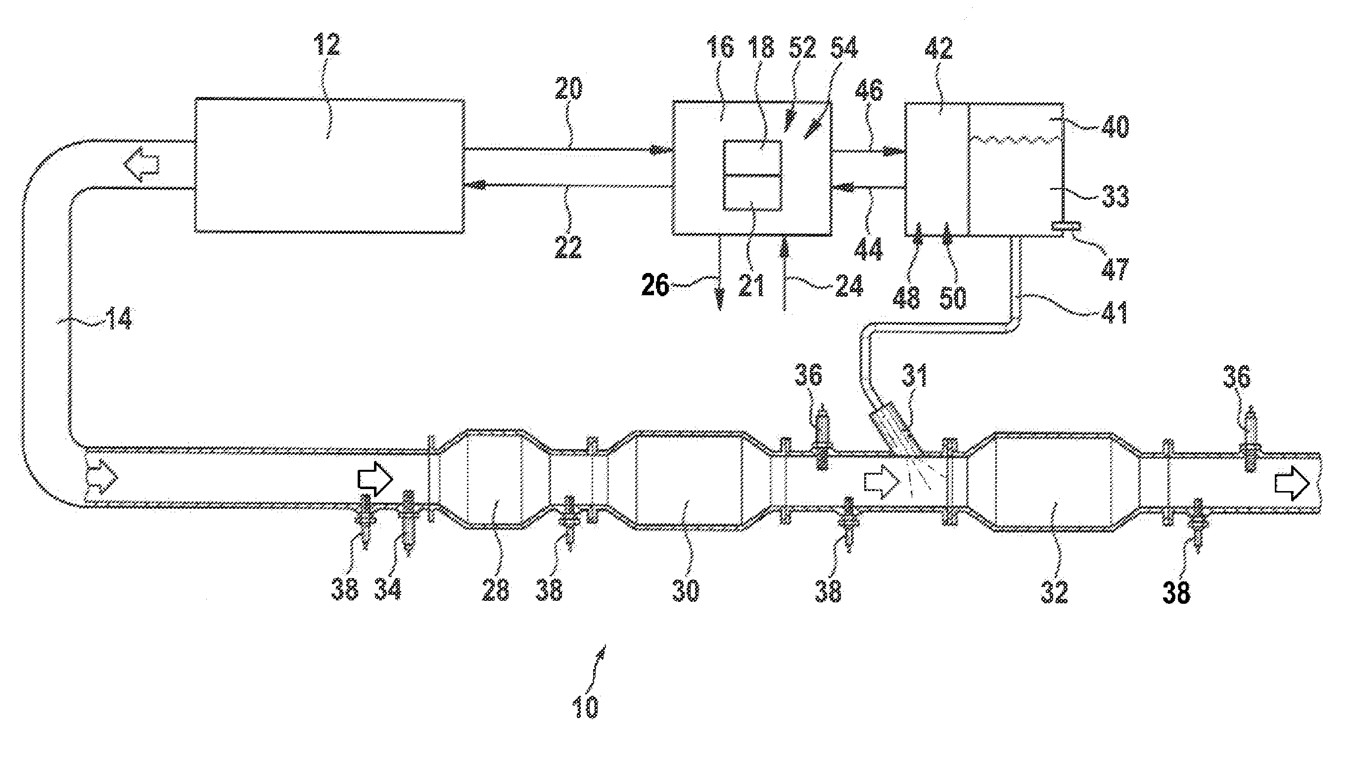
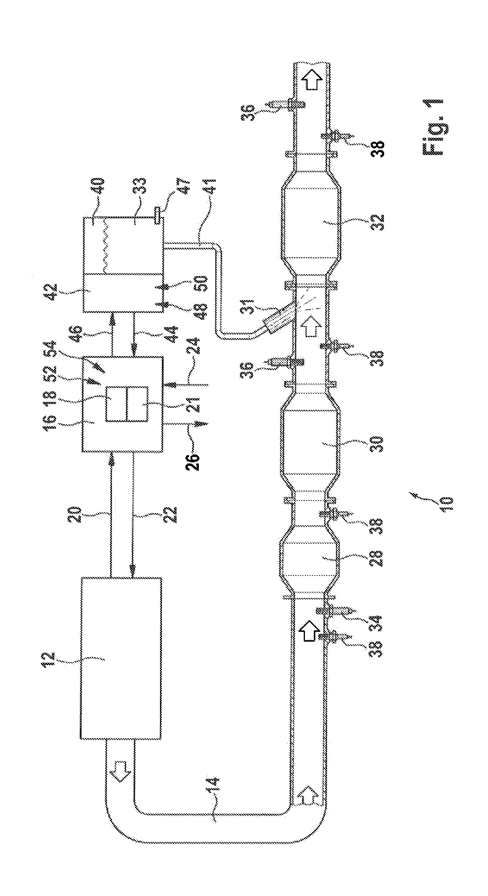
[0041]FIG. 1 shows a simplified diagram of an exhaust gas system 10 of a motor vehicle in the lower section of the drawing. An internal combustion engine 12 is symbolically depicted on the left above the exhaust gas system, said combustion engine discharging exhaust gas into the exhaust gas system 10 via a pipe connection 14. An open-loop and / or closed loop control device 16 is connected via incoming and outgoing electrical lines 20 and 22 to said combustion engine 12 as well as via incoming and outgoing electrical lines 24 and 26 to components of the exhaust gas system 10. The connections are merely indicated in the drawing. The open-loop and / or closed-loop control device 16 further comprises a computer program 18 and one or a plurality of characteristic diagrams 21. The computer program 18 can exchange data with the characteri...


PUM


Abstract

A method for operating an exhaust gas system of an internal combustion engine is described, wherein NOx is reduced by means of a SCR catalyst and a NOx reduction capability of an aqueous urea solution to be introduced into the exhaust gas system is monitored, and wherein at least one first variable characterizing the ammonia content of the water is ascertained and an ageing of the aqueous urea solution is inferred from said first variable.

Description

BACKGROUND OF THE INVENTION[0001]The invention relates to a method for operating an exhaust gas system of an internal combustion engine.[0002]Internal combustion engines, particularly diesel engines which reduce nitrogen oxides (NOx) present in the exhaust gas of the internal combustion engine by means of selective catalytic reduction (SCR), are known from the market. The NOx reduction takes place, for example, by means of ammonia (NH3) being introduced into the exhaust gas or respectively into the SCR catalyst. A patent publication from this subject area is, for example, DE 10 2009 029 107 A1.SUMMARY OF THE INVENTION[0003]The invention has, among others, the advantage that an ageing of an aqueous urea solution for reducing nitrogen oxides in the exhaust gas of an internal combustion engine can be determined. A NOx reduction capability of the aqueous urea solution can especially be determined from a first variable characterizing the ammonia content in the water and a second variable...

Claims


Application Information

Patent Timeline
Patent Type & Authority Applications(United States)
IPC IPC(8): F02C9/16
CPCF02C9/16Y02T10/24F01N3/0821F01N3/106F01N3/208F01N11/00F01N2550/05F01N2560/025F01N2560/026F01N2560/06F01N2560/14F01N2610/02F01N2900/1806F01N2900/1818F01N13/009Y02T10/47Y02T10/12Y02T10/40
Inventor NEUMANN, JOERGHANDLER, TORSTENWENDT, HAUKEPFISTER, TOBIAS
Owner ROBERT BOSCH GMBH
Why Eureka
Try Eureka