Disc Brake for a Motor Vehicle, Having a Sealing Arrangement Designed for an Electronic Parking Brake

a technology of electronic parking brake and disc brake, which is applied in the direction of axially engaging brakes, brake systems, mechanical devices, etc., can solve the problems of insufficient force, no longer acting hydraulic pressure, and significant interaction difficulties, and achieves simple and cost-effective means.

Active Publication Date: 2016-06-16
LUCAS AUTOMOTIVE GMBH
View PDF14 Cites 3 Cited by
  • Summary
  • Abstract
  • Description
  • Claims
  • Application Information

AI Technical Summary

Benefits of technology

[0009]A feature of the present invention is to provide a disc brake of the type described at the beginning in which a clearance can be obtained by simple and cost-effective means even upon activation of the parking brake via the actuator and subsequent release of the same.

Problems solved by technology

In this context it was recognised that conventional sealing arrangements, in which a sealing ring is simply inserted into a corresponding annular groove, can lead to significant difficulties in the interaction between instances of service braking and activations of the parking brake function carried out in the interim.
Hydraulic pressure no longer acts upon the sealing ring on the hydraulic chamber side and it is accordingly not sufficiently strongly deformed and pressed against the external circumferential surface of the actuating piston to maintain the adhesive friction, as is the case in normal service braking.
The risk accordingly arises when activating the parking brake via the actuator that when the actuating piston moves, it overcomes the adhesive friction between actuating piston and sealing ring and ultimately slips through the sealing ring by a certain distance.
If the parking brake is later released again, the sealing ring no longer provides the elastic reset movement that is usually effective during service braking due to this slipping through.
As a consequence, residual abrading torques that are considerable in some cases and are accompanied by disadvantages such as pad wear, increased fuel consumption, noise emission etc. occur following the actual release of the parking brake.
In this solution, however, the occurrence of residual abrading torques following the activation of the parking brake is counteracted not by configuration of the annular groove, but rather by targeted use of a slip control system.

Method used


Image

  • Disc Brake for a Motor Vehicle, Having a Sealing Arrangement Designed for an Electronic Parking Brake
  • Disc Brake for a Motor Vehicle, Having a Sealing Arrangement Designed for an Electronic Parking Brake
  • Disc Brake for a Motor Vehicle, Having a Sealing Arrangement Designed for an Electronic Parking Brake

Examples


Embodiment Construction

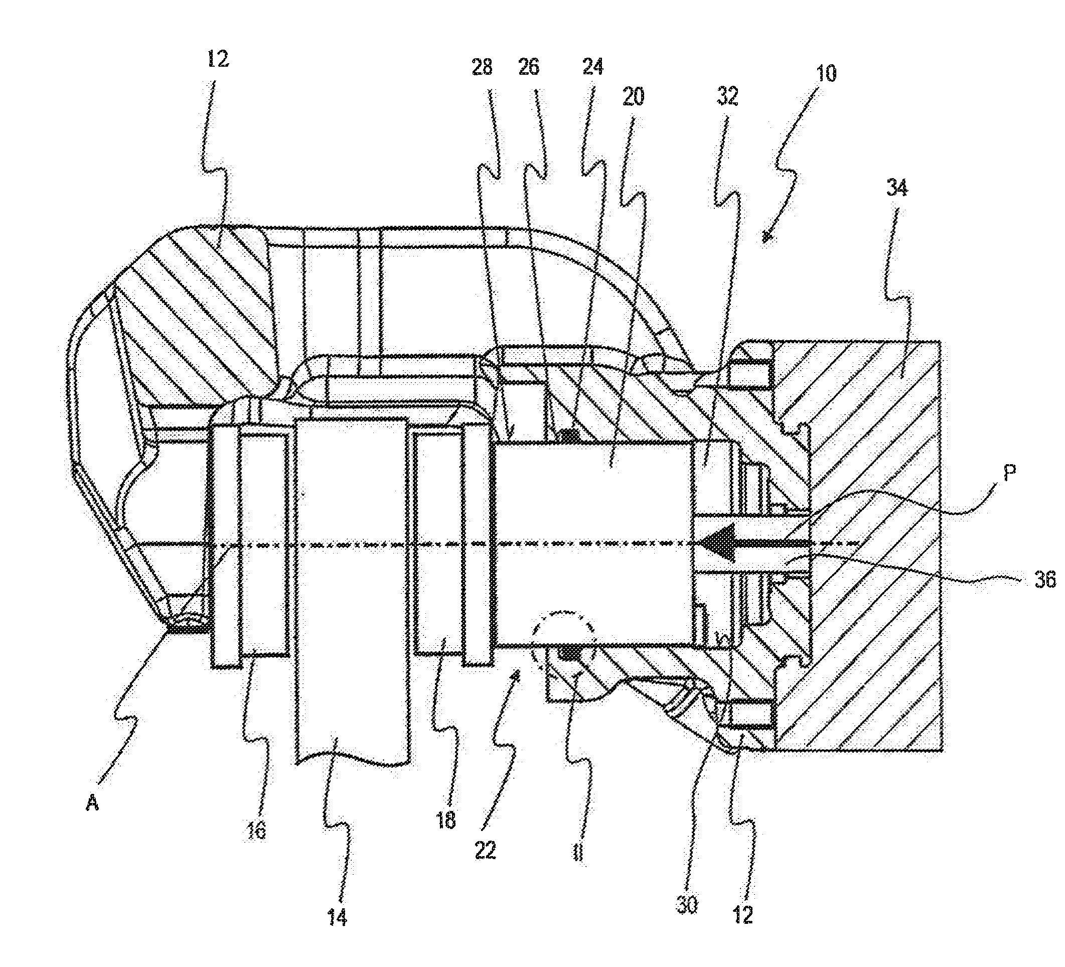
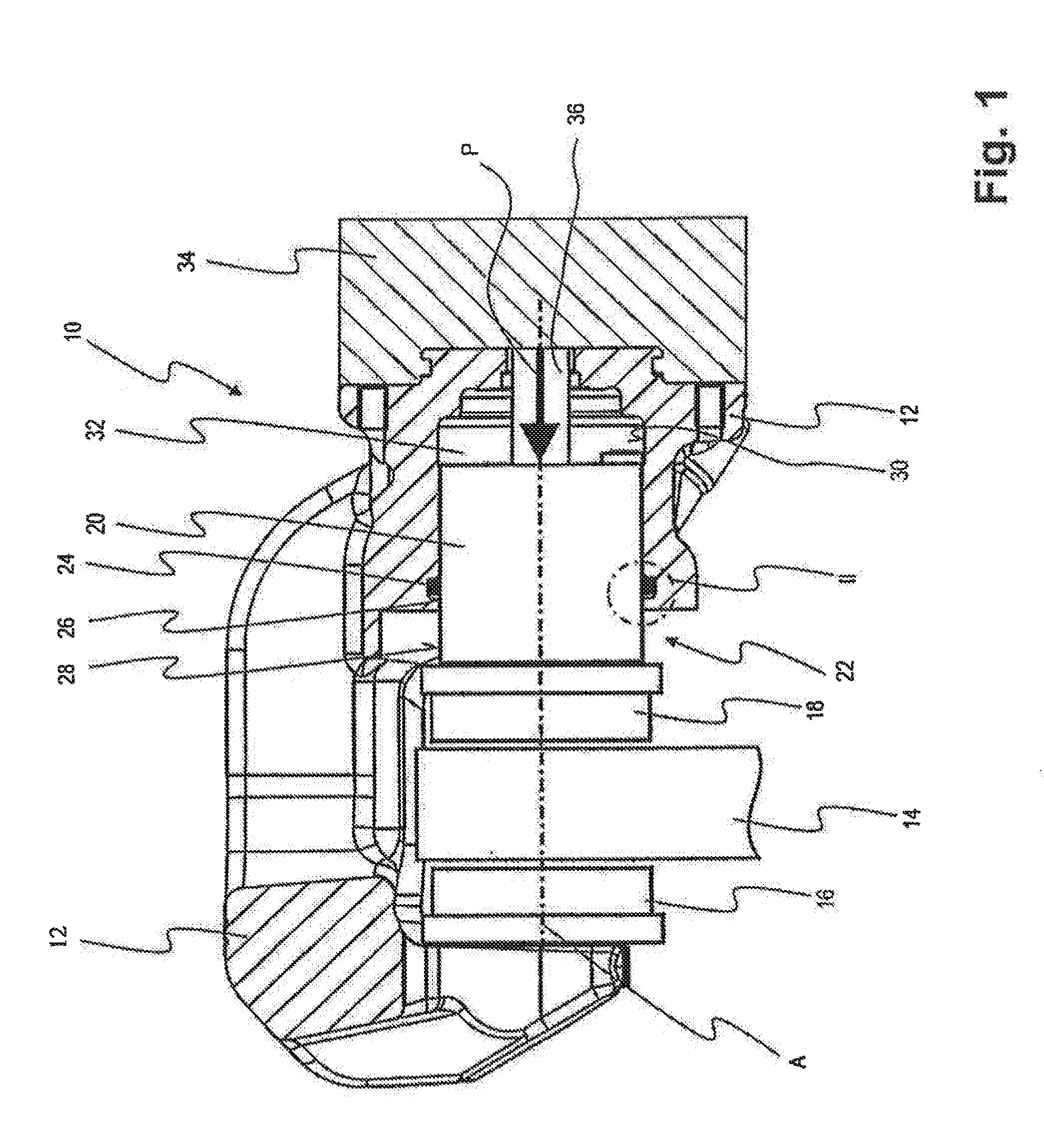
[0025]FIG. 1 shows a disc brake according to the invention in a sectional view containing the axis and generally designated 10. This is formed in the form of a brake calliper and comprises a housing 12, which spans a brake disc 14 connected non-rotatably to a vehicle wheel in a known manner. A brake pad 16 as well as another brake pad 18 is supported in the housing 12. The brake pad 18 is movable in the housing 12 by means of an actuating piston 20, which is movable along a piston longitudinal axis A according to the arrow P.

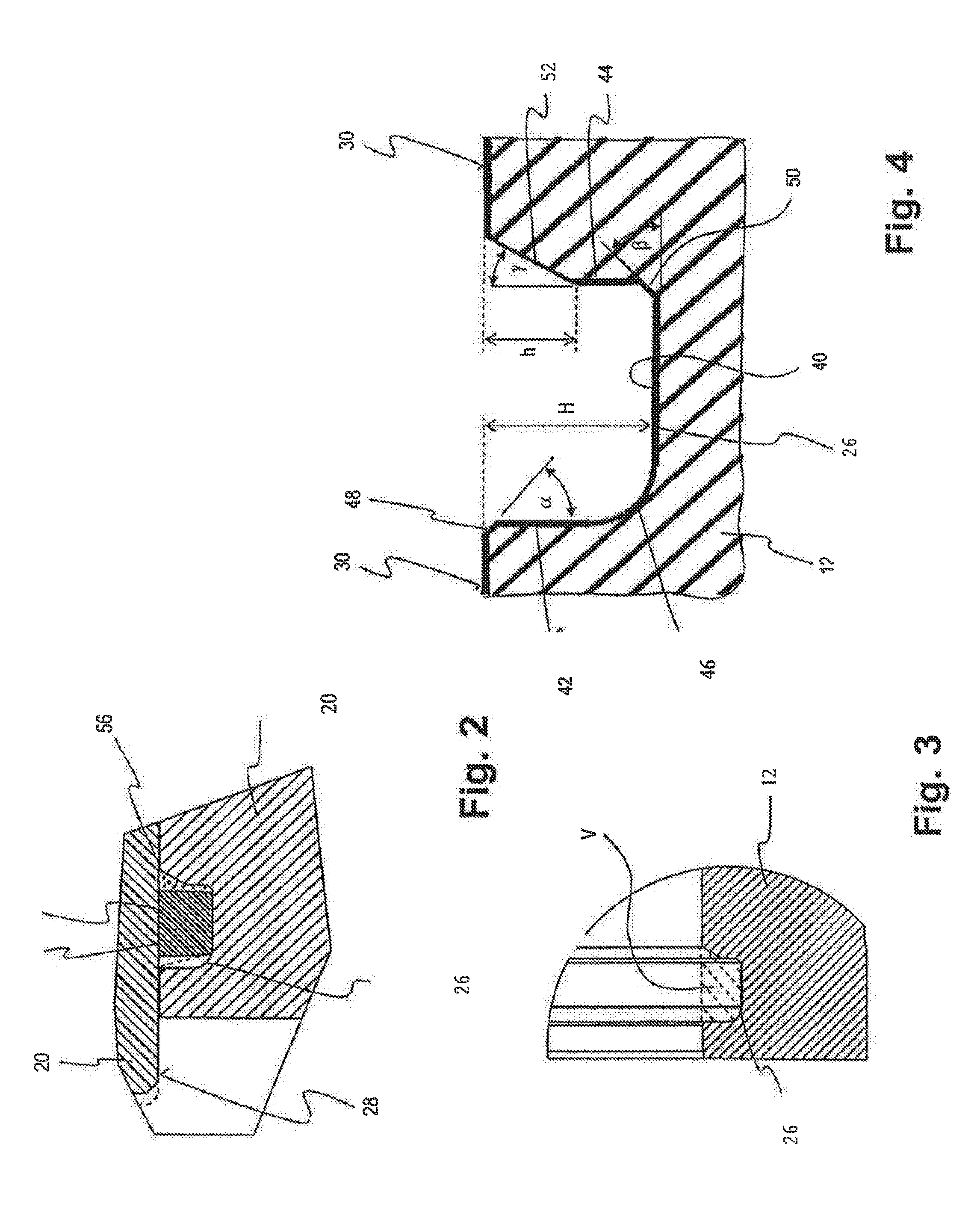
[0026]The actuating piston 20 is part of an actuation device 22, which can be actuated optionally hydraulically or electromechanically. For hydraulic actuation it is provided that the actuating piston 20 is guided movably in a piston receptacle opening 30 in a sealing manner by means of a sealing ring 24, which is taken up in an annular groove 26, on its external circumferential surface 28. Together with the actuating piston 20, the piston receptacle opening 30 ...


PUM


Abstract

A disc brake for a motor vehicle, wherein it is possible to displace the actuating piston in the housing both by hydraulic pressure activation of a hydraulic chamber formed in the housing and via a mechanical actuator, wherein the sealing ring is accommodated in an annular groove formed in the housing. Provision is made here for the annular groove to have a groove floor, which runs substantially parallel to the longitudinal axis of the piston, and two groove walls, which adjoin the groove floor, wherein as seen in the direction of the longitudinal axis of the piston a first groove wall is directed away from the hydraulic chamber and a second groove wall is directed towards the hydraulic chamber, wherein the first groove wall merges into the groove floor via a rounded or bevelled transition region at a varying distance from the longitudinal axis of the piston.

Description

CROSS-REFERENCE TO RELATED APPLICATIONS[0001]This application is a national stage of International Application No. PCT / EP2014 / 065698 filed Jul. 22, 2014, the disclosures of which are incorporated herein by reference in entirety, and which claimed priority to German Patent Application No. 10 2013 012 823.4 filed Aug. 1, 2013, the disclosures of which are incorporated herein by reference in entirety.BACKGROUND OF THE INVENTION[0002]The present invention relates to a disc brake for an automotive vehicle, wherein the disc brake comprises a housing, a brake disc rotatable relative to the housing, at least one friction pad, and at least one actuation device, which is formed to effect a relative movement between the brake disc and the friction pad, such that the friction pad can be brought into contact with the brake disc, wherein the actuation device has at least one actuating piston movable along a piston longitudinal axis, which actuating piston is guided in a hydraulically sealing mann...

Claims


Application Information

Patent Timeline
Patent Type & Authority Applications(United States)
IPC IPC(8): B60T1/06F16J15/16F16D65/18
CPCB60T1/065F16D65/18F16J15/164F16D2125/08F16D2121/02F16D2121/18F16D2123/00F16D2127/02F16J15/56
Inventor STAHL, PETERKUHNERT, BORISDAMRAU, CHRISTIANTHARR, CHRISTIANPODZUWEIT, DIETRICHHEINEMANN, MARIABRANDT, MARTINDANG, NONGSCHOG, MICHAEL
Owner LUCAS AUTOMOTIVE GMBH
Why Eureka
Try Eureka