Charging frame and quenching device having a charging frame

a charging frame and charging device technology, applied in the field of charging frames, can solve the problems of less effective quenching of the lower layer of parts and higher blower output, and achieve the effects of preventing the flow of quenching gas out of the charging frame, simple and cost-effective means, and increasing the intensity of quenching

Inactive Publication Date: 2014-12-02
ROBERT BOSCH GMBH
View PDF25 Cites 0 Cited by
  • Summary
  • Abstract
  • Description
  • Claims
  • Application Information

AI Technical Summary

Benefits of technology

[0007]An object of the present invention is to increase the quenching intensity through simple and cost-effective means. The present invention is based on the idea of providing the charging frame with a circumferentially closed peripheral wall in such a way that lateral flow of quenching gas out of the charging frame is prevented. In other words, the charging frame is closed on the side; i.e., a kind of flow channel which prevents quenching gas from flowing out of the charging frame on the side of the parts is provided with the aid of the charging frame. The concentration of quenching gas flows achieved by providing the circumferentially closed peripheral wall makes it possible to achieve higher flow rates within the entire batch, consequently resulting in a higher quenching intensity. The peripheral wall is preferably dimensioned in the flow direction in such a way that the parts do not project over the peripheral wall. In contrast to the quenching device proposed in published European patent document EP 1 154 024 B1, the peripheral wall in a charging frame designed according to the concept of the present invention is an integral part thereof and does not have to be adjusted relative to the charging frame within the quenching chamber, which results on the whole in a much simpler construction of a quenching device provided with a charging frame described above. In particular, the circumferentially closed peripheral wall is preferably fixedly connected to a platform for holding the parts.
[0011]The provision of a circumferentially closed peripheral wall, as described above, makes it possible to design or load the at least one, preferably only one, platform in such a way that the freely passable surface portion is less than 0.6 (in relation to the total area of the platform). It is particularly preferred if the freely passable surface portion is selected from a value range between 0.4 and 0.5 to ensure optimum charging, i.e., batch size. Implementing a small, freely passable cross-sectional area of this type permits much higher flow rates yet also results in correspondingly high pressure losses within the batch which, in turn, are acceptable due to the circumferentially closed peripheral wall.
[0012]A specific embodiment of the charging frame is particularly preferred in which the parts are freely situated within the peripheral wall, i.e., no separate flow channels are provided within the peripheral wall for each individual workpiece to be cooled. This embodiment results in a very simple charging frame construction and also enables the at least one, preferably only one, platform to be quickly loaded and unloaded. By dispensing with intermediate walls, which take up a lot of space, within the peripheral wall, it is possible to cool large batch sizes. In addition, this results in the advantage of easier loading, since the entire batch may be loaded and unloaded at once. The individual flow channels within the peripheral wall are preferably exclusively formed by the parts themselves, it being particularly preferred to space the parts a constant distance from each other and / or from the peripheral wall.
[0014]A combination of the conducting means situated in an area between the charging frame and the flow channel and a charging frame designed as described above, which has a circumferentially closed peripheral wall, is very particularly preferred. The conducting means and the circumferentially closed peripheral wall are combined into a common flow channel situated within the quenching chamber, which prevents lateral flow of the quenching gas out of the charging frame. In other words, a construction of this type completely prevents bypass flows to the outside, and the entire volumetric flow is conducted through the batch without the need to provide a hood which has adjustable flow channels for each workpiece and which is situated within the quenching chamber. If the peripheral wall projects over the platform on both sides, the conducting means may also be formed by the section of the peripheral wall which projects downward from the platform, i.e., in the flow direction.
[0016]To optimize the efficiency of the quenching device, a specific embodiment is preferred in which a heat exchanger is situated in the flow circuit and may be used to remove the heat which has been selectively absorbed via the quenching gas.
[0018]In a refinement of the present invention, it is advantageously provided that the at least one, preferably the only one, blower is equipped with a rotational speed control device, preferably a frequency converter, for the purpose of limiting the starting currents. This offers the additional advantage that the blower output, and thus the flow rate, may be adapted to the required heat transfer coefficient of the particular batch.

Problems solved by technology

However, a specific embodiment is very particularly preferred in which charging is carried out using only one layer of parts, since additional layers increase pressure loss and thus necessitate an even higher blower output.
In addition, it has become apparent that the lower layers of parts are usually less effectively quenched.

Method used


Image

  • Charging frame and quenching device having a charging frame
  • Charging frame and quenching device having a charging frame
  • Charging frame and quenching device having a charging frame

Examples


Embodiment Construction

[0022]In the figures, the same components and components having the same function are identified by the same reference numerals.

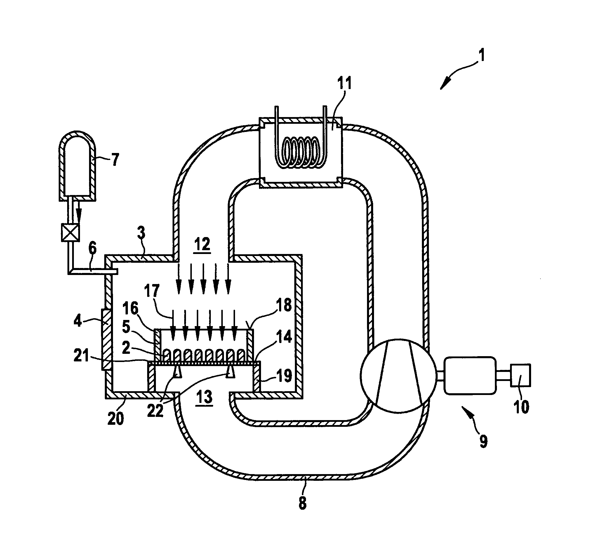
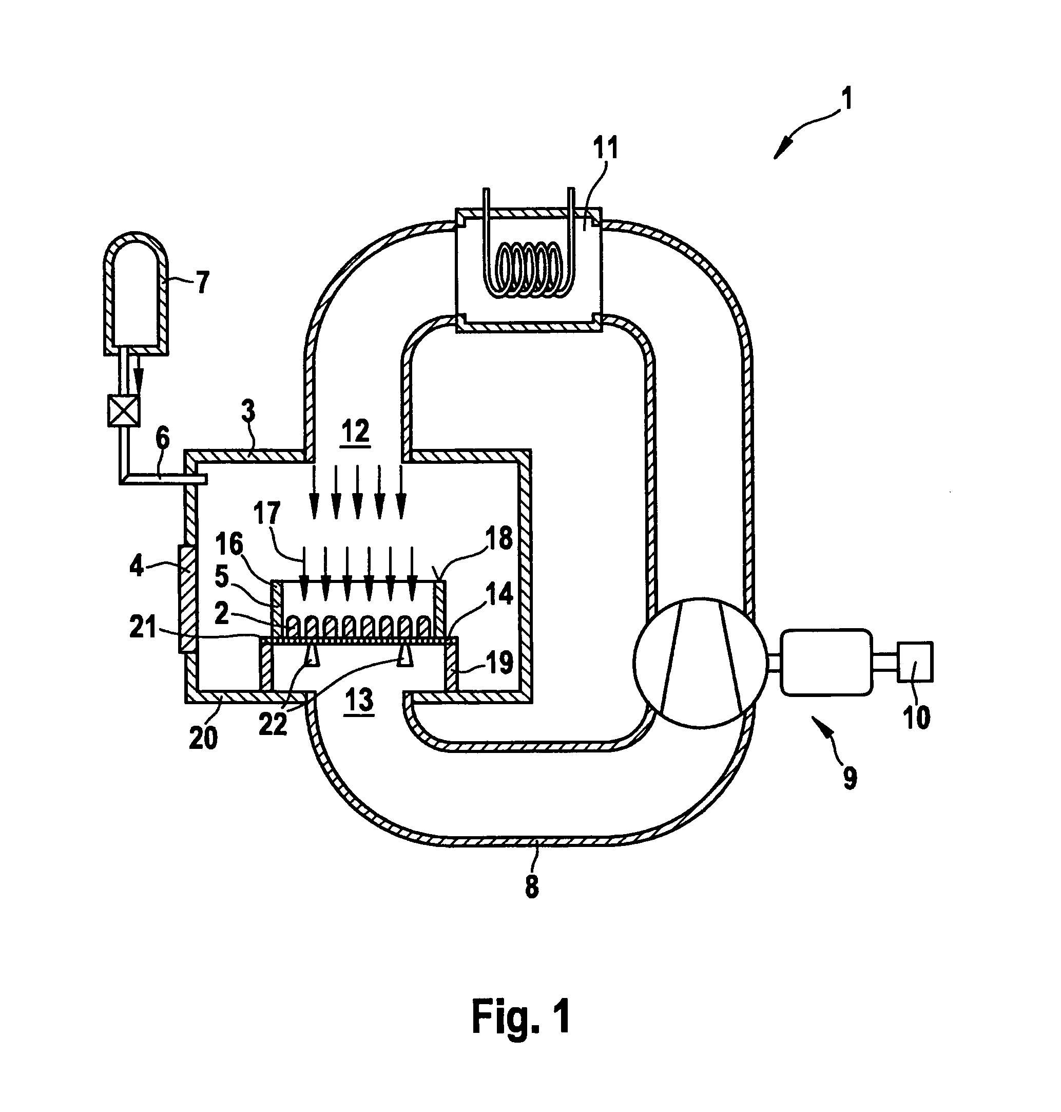
[0023]FIG. 1 shows a quenching device 1 for quenching parts 2, in this case metal workpieces. Quenching device 1 includes a quenching chamber 3 which has a pressure-tight door 4 (loading door) for loading and unloading quenching chamber 3 with the aid of a charging frame 5 which carries parts 2 and is made of a carbon fiber-reinforced carbon. A pressure gas line 6 for supplying quenching gas from a high pressure tank 7 empties into quenching chamber 3.

[0024]A flow channel 8, which forms a flow circuit for the quenching gas together with quenching chamber 3, is fluidically connected to quenching chamber 3.

[0025]A blower 9, which is designed as a radial blower, is situated in flow channel 8, a rotational speed control device 10 being assigned to this blower 9.

[0026]A heat exchanger 11 for removing heat from the quenching gas is furthermore located in flow cha...


PUM

PropertyMeasurementUnit
pressureaaaaaaaaaa
heataaaaaaaaaa
rotational speedaaaaaaaaaa

Abstract

A charging frame for accommodating a batch of parts to be quenched, e.g., metal workpieces, has a circumferentially closed peripheral wall which surrounds the batch and thereby forms a flow channel which prevents bypass flows. The charging frame is a part of a quenching device.

Description

BACKGROUND OF THE INVENTION[0001]1. Field of the Invention[0002]The present invention relates to a charging frame for accommodating a batch of parts to be quenched with the aid of a quenching gas, and also relates to a quenching device for quenching the parts, in particular metal workpieces.[0003]2. Description of Related Art[0004]To produce defined workpiece properties, such as a high degree of hardness or a sufficient wear resistance, most metal workpieces are subjected to heat treatment. The speed at which the previously heated workpieces are cooled is important for the treatment result. The use of water, oil or quenching gas is known for the necessary quenching process. The main advantage of using quenching gases instead of quenching liquids is the fact that the parts do not have to be cleaned following quenching as well as the fact that a higher quenching homogeneity within the batch may be achieved. However, to increase the quenching intensity to be achieved with the aid of qu...

Claims


Application Information

Patent Timeline
Patent Type & Authority Patents(United States)
IPC IPC(8): C21D9/00C21D1/767
CPCC21D9/0025C21D1/767
Inventor MUELLER, BERNHARD
Owner ROBERT BOSCH GMBH
Why Eureka
Try Eureka