Utility food grater

a technology of food grater and grater plate, which is applied in the direction of grater, solid separation, kitchen equipment, etc., can solve the problems of limited size and shape of food products that may be grated, uncomfortable and cumbersome use of typical prior art food grater, and difficult task of grating food products such as cheese or vegetables

Inactive Publication Date: 2005-03-01
RICHARDSON MICHAEL TYLER
View PDF5 Cites 42 Cited by
  • Summary
  • Abstract
  • Description
  • Claims
  • Application Information

AI Technical Summary

Benefits of technology

A grater and method for grating, wherein a grating panel is connected to a handle with a gripping portion aligned behind the grating surface back side below the top end and above the bottom end and in a common plane with the directional vector, the gripping portion further forming an angle with the downward directional vector, the gripping portion vector angle less than 90 degrees. It is preferred that the ang

Problems solved by technology

Grating food products, such as cheese or vegetables, is not always an easy task.
Typical prior art food graters can be uncomfortable and cumbersome to use.
With respect to the rotary-style, the size and shape of the food products that may be grated are limited by the size of the intake structure, which is usually a relatively small rectangular chute.
Use of the gravity-feed style is also limited to small food products that freely pour through the chute to engage the drum.
And both the mechanical and box style prior art graters are fairly difficult and time consuming to clean, the former as there are a lot of moving parts that need to be washed when finished, and the latter due to cumbersome access to the internal “boxed” area.
Dishes or cutting boards must be washed when finished, or paper towels must be thrown away, resulting in cumbersome inefficiencies.
It is also inconvenient to grate some food product onto a first collector and then transfer th

Method used


Image

  • Utility food grater
  • Utility food grater
  • Utility food grater

Examples


Embodiment Construction

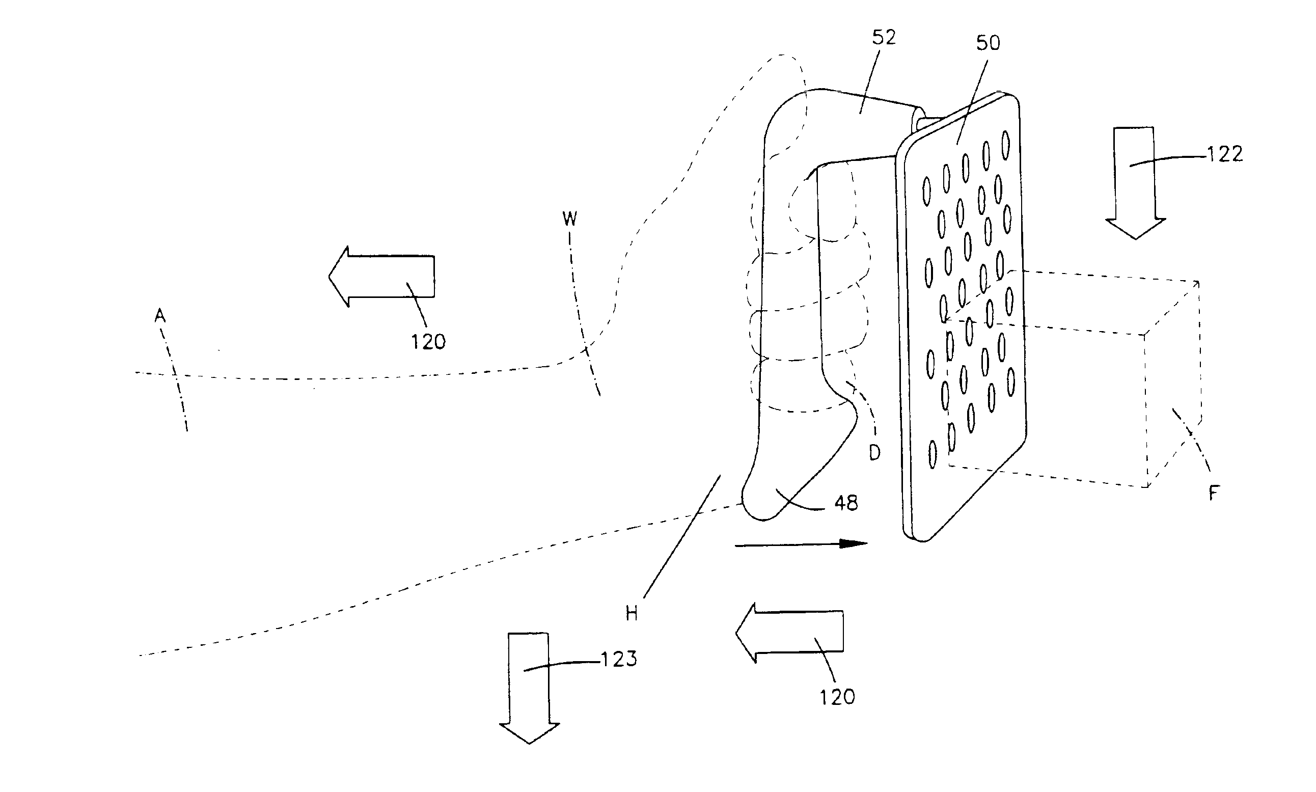
FIGS. 4, 5, 6, and 7 provide front, back, side, and bottom views, respectively, of a grater 48 according to the present invention. A planar rectangular flat grating panel 50 is attached to a handle 52 attached by a continuous looped rod 54. The panel forms a plurality of cutting blades 53 and associated apertures 51 for grating foods drawn downward across the panel 50. It is preferred that the panel 50 is formed from stainless steel, although other materials may be apparent to one skilled in the art. Although, in this embodiment, the panel 50 has a flat planar rectangular structure, it may also be curved, or it may be triangular or oval. Other shapes will be readily apparent to one skilled in the art. The rod 54 is preferably made out of stainless steel, although other materials may be apparent to one skilled in the art. The panel 50 is preferably made out of a metallic material, such as stainless steel, and is attached to the rod 54 by wrapping the edges 56 of the panel 50 around t...


PUM


Abstract

A grater and method for grating, wherein a grating panel is connected to a handle with a gripping portion aligned behind the grating surface back side below the top end and above the bottom end and in a common plane with the directional vector, the gripping portion further forming an angle with the downward directional vector, the gripping portion vector angle less than 90 degrees. It is preferred that the angle is selected to translate forces normal to and against the grating surface front side into compressive forces against a user's hand gripping the handle gripping portion. In one embodiment, the connecting means is a steel rod disposed along the panel edge portions and projects from the panel top normal to the planar panel. Some embodiments have stand elements to enable the grater to stand upon a work-surface.

Description

FIELD OF THE INVENTIONThe present invention relates to hand tools and, in particular, to devices for use in food preparation, more particularly to food graters.BACKGROUND OF THE INVENTIONGrating food products, such as cheese or vegetables, is not always an easy task. Typical prior art food graters can be uncomfortable and cumbersome to use. Prior art graters may be categorized into three basic styles. The first style is the “single flat panel style,” which typically has a flat rectangular planar panel with grating elements defining a “grating area” and a handle attached to the top of the planar panel extending upward in the same plane. One example of this style is the Williams-Sonoma, Inc. “Stainless Steel Flat Grater.” This grater style is typically used to grate food above a bowl or other distribution area, and is often rested on a work surface for additional support.The second style is the “box style” grater. This style typically has three or four planar panels with grating eleme...

Claims


Application Information

Patent Timeline
IPC IPC(8): A47J43/00A47J43/25
CPCA47J43/25
Inventor RICHARDSON, MICHAEL TYLER
Owner RICHARDSON MICHAEL TYLER
Why Eureka
Try Eureka