
Wheelchair ramp with side barriers

a technology for wheelchairs and ramps, applied in the field of wheelchair ramps with side barriers, can solve the problems of limited use of spring-released barriers and the inability to achieve low-profiles

Inactive Publication Date: 2005-03-01
BRAUN THE
View PDF49 Cites 23 Cited by
  • Summary
  • Abstract
  • Description
  • Claims
  • Application Information

AI Technical Summary

Benefits of technology

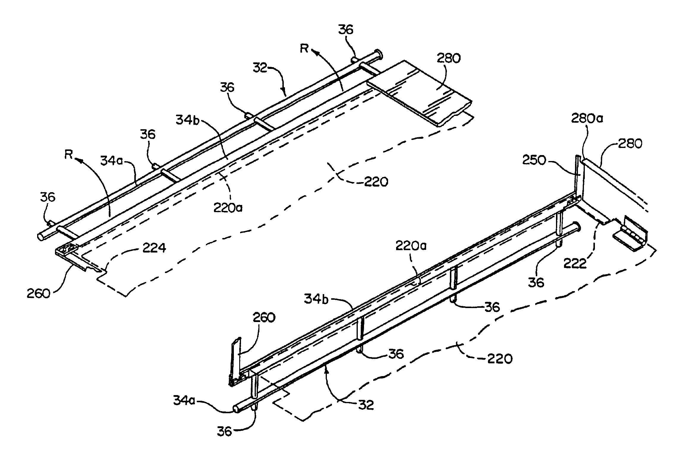
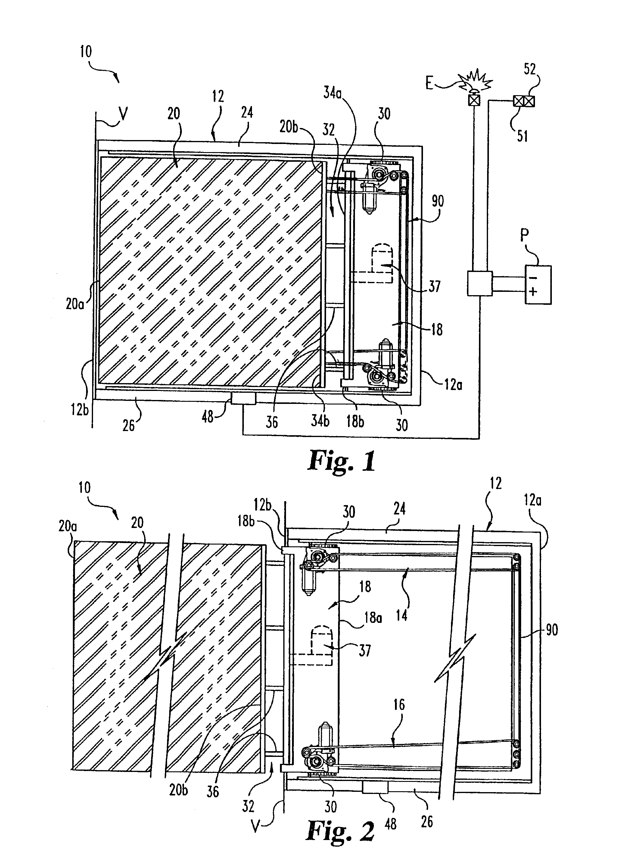
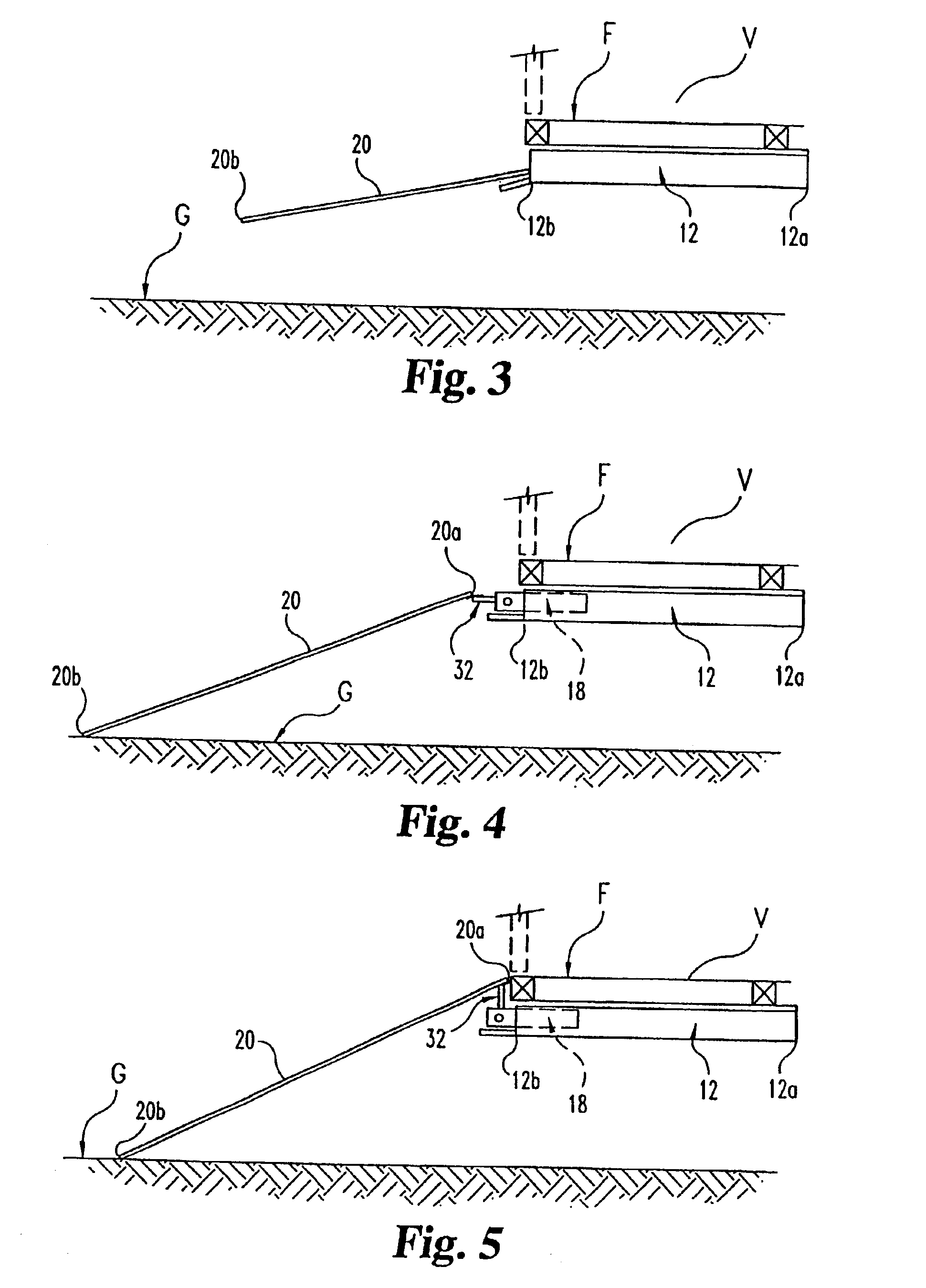
The present invention is a vehicular access system that includes a ramp for transferring wheelchairs between the ground and a vehicle. The ramp has side barriers that can be raised to a safety barrier position or lowered to a low-profile position. The side barriers are pivoted from the low-profile position to the raised safety barrier position by an actuator that comes into contact with each side barrier. The actuator remains in contact with its adjacent side barrier to support it in the raised safety barrier position. The system also includes a rocker assembly and a drive assembly for raising the ramp and pivoting the side barrier. The technical effect of this invention is to provide a more convenient and safe way to transfer wheelchairs between the ground and a vehicle.

Problems solved by technology

Whereas the prior art discloses side barriers fixedly-mounted or deployable with the ramp, several problems are associated with the prior art systems in that low-profiles may only be achieved with fixed barriers where the barrier height is of limited useful dimensions.
On the other hand, spring-released barriers may be of limited use where the resilient spring actuation is susceptible to being defeated with obstacles or failure of the spring-actuated mechanism itself.

Method used


Image

  • Wheelchair ramp with side barriers
  • Wheelchair ramp with side barriers
  • Wheelchair ramp with side barriers

Examples


Embodiment Construction

For the purposes of promoting an understanding of the principles of the invention, reference will now be made to the embodiment illustrated in the drawings and specific language will be used to describe the same. It will nevertheless be understood that no limitation of the scope of the invention is thereby intended. Any such alterations and further modifications in the illustrated device, and such further applications of the principles of the invention as illustrated herein are contemplated as would normally occur to one skilled in the art to which the invention relates.

Referring now to FIG. 1 there is illustrated a vehicular access system 10 according to the present invention. Access system 10 includes a frame 12 having an inboard end 12a and an opposite outboard end 12b. Frame 12 can be mounted to a vehicle V either below the vehicle floor, or in any other position on the vehicle as would occur to those skilled in the art. A transfer member is movably mounted to the frame and is s...


PUM


Abstract

An access system for passenger boarding of a vehicle is provided. The access system includes a frame mounted to the vehicle. A ramp is movably mounted in the frame. The ramp is movable with respect to the frame between a stowed position and a deployed position with respect to the vehicle. The ramp includes side barriers extending therealong between an inboard end and an outboard end of the ramp. The side barriers are movable between a stowed orientation and a raised safety barrier orientation by an actuator. The vehicular access system includes a frame positioned below the floor level of a vehicle to which a carriage is moveably mounted. The ramp or transfer member is attached to the carriage by a pivoting rocker assembly. A drive assembly deploys and stows the ramp from the frame. An actuator is moveable between a raised safety barrier orientation and a stowed low-profile orientation with a side barrier that is pivotably mounted and spring biased toward the stowed low-profile orientation. The rocker assembly and actuator are operable with the drive assembly to raise the inboard end of the ramp to the floor level of the vehicle and to pivot the side barrier to the raised safety barrier orientation as the ramp is deployed.

Description

BACKGROUND OF THE INVENTION1. Field of the InventionThe present invention relates generally to the field of vehicular access systems, and more particularly to a wheelchair ramp with side barriers.2. Description of the Related ArtVehicular wheelchair access systems for handicapped persons, such as lifts and ramps, can be mounted on vehicles and deployable / stowable with respect to the vehicle. Wheelchair users typically must move their wheelchair along lift platforms and ramps in order to transfer from the ground to the vehicle and from the vehicle to the ground. Sidebarriers can be provided along the length of the ramp or lift platform as a safety precaution to prevent a wheelchair from moving or exiting over the sides of the ramp or platform outside the vehicle. Such sidebarriers may be affixed or deployable with the ramp. Examples of wheelchair ramps with side barriers are provided in U.S. Pat. No. 5,393,192 to Hall, et al. for “Underfloor Extendable Ramp for Vehicles” issued Feb. ...

Claims


Application Information

Patent Timeline
Patent Type & Authority Patents(United States)
IPC IPC(8): A61G3/00A61G3/06B60P1/00B60P1/43
CPCA61G3/061B60P1/431A61G2003/067Y10S414/134A61G3/067
Inventor KISER, AARON
Owner BRAUN THE
Learn More