
Modular appliance

a technology of modular appliances and appliances, applied in the direction of kitchen equipment, application, coupling device connections, etc., can solve the problems of crowding and clutter in the kitchen

Inactive Publication Date: 2005-03-01
SEEFF STANLEY JOSEPH
View PDF22 Cites 72 Cited by
  • Summary
  • Abstract
  • Description
  • Claims
  • Application Information

AI Technical Summary

Problems solved by technology

This leads to crowding and clutter in the kitchen.

Method used


Image

  • Modular appliance
  • Modular appliance
  • Modular appliance

Examples


Embodiment Construction

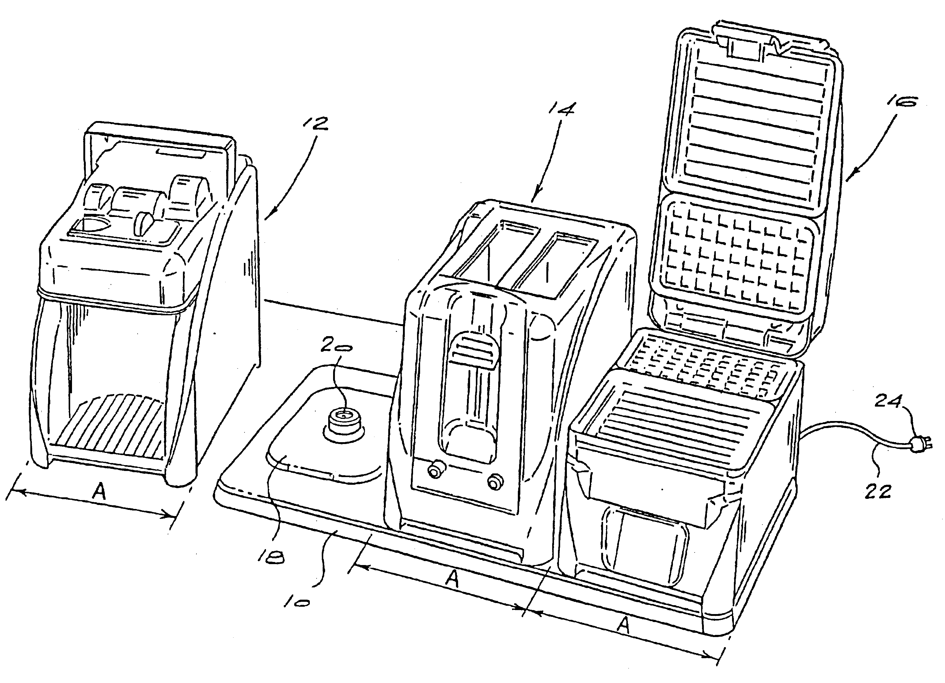
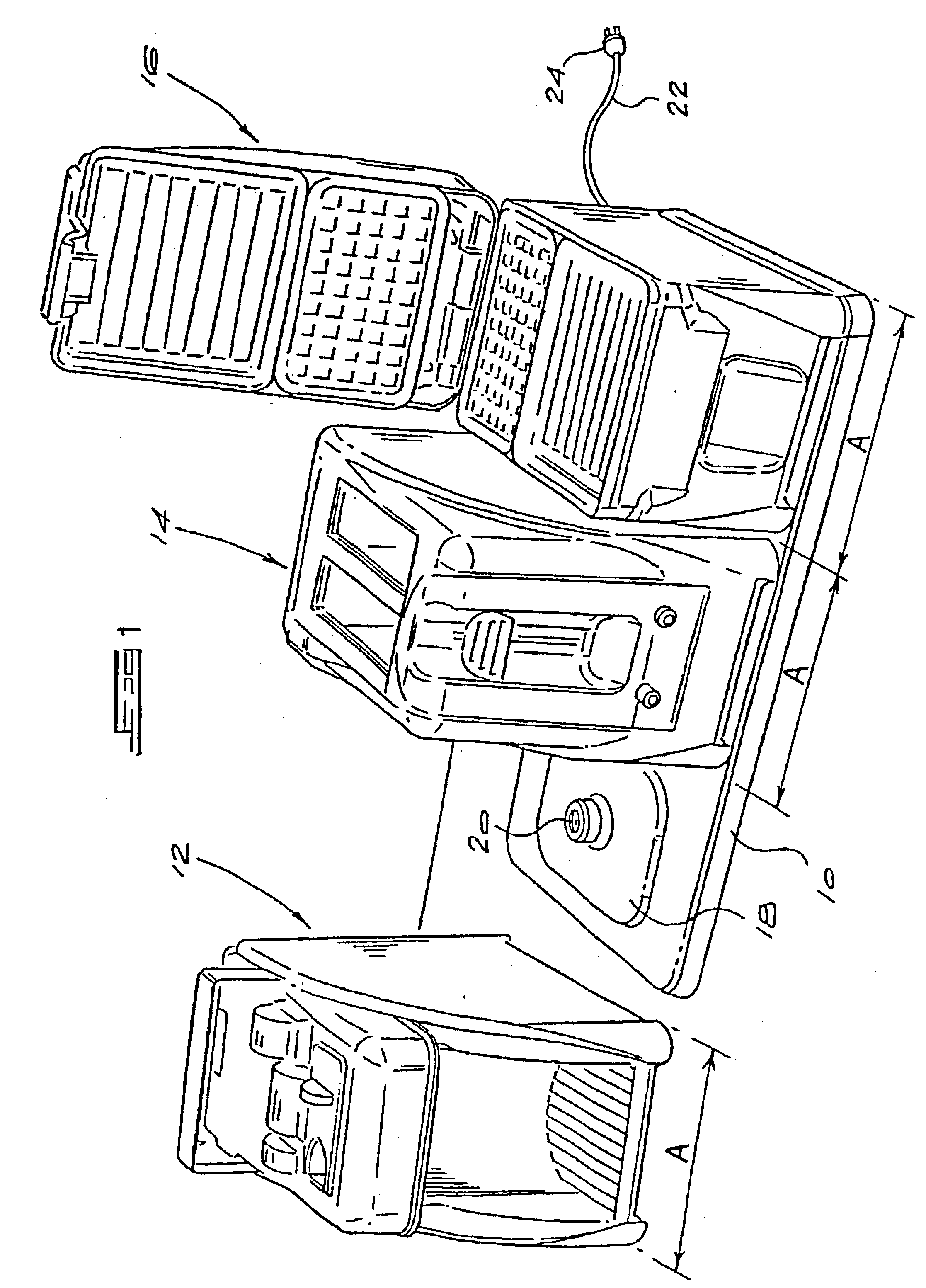
The modular appliance system illustrated in FIG. 1 comprises a generally planar base unit 10 which is moulded from a suitably tough and heat resistant plastics material such as polypropylene, and a set of modular appliances 12, 14 and 16 which can be mounted on the base unit individually or together, side by side. The base can be formed from other suitable plastics, or other materials including metals such as stainless steel, or natural materials such as marble or wood.

In FIG. 1, the appliance 12 is a hot water dispensing unit, the appliance 14 is a toaster, and the appliance 16 is a sandwich toaster / waffle iron. It will be appreciated that the illustrated appliances are merely exemplary, and that the set of appliances usable on the base 10 may include various other appliances, or more than one identical appliance.

The base 10 is rectangular and is provided with a plurality of locating formations in the form of upstanding rectangular lands 18 having rounded corners, each of which has...


PUM


Abstract

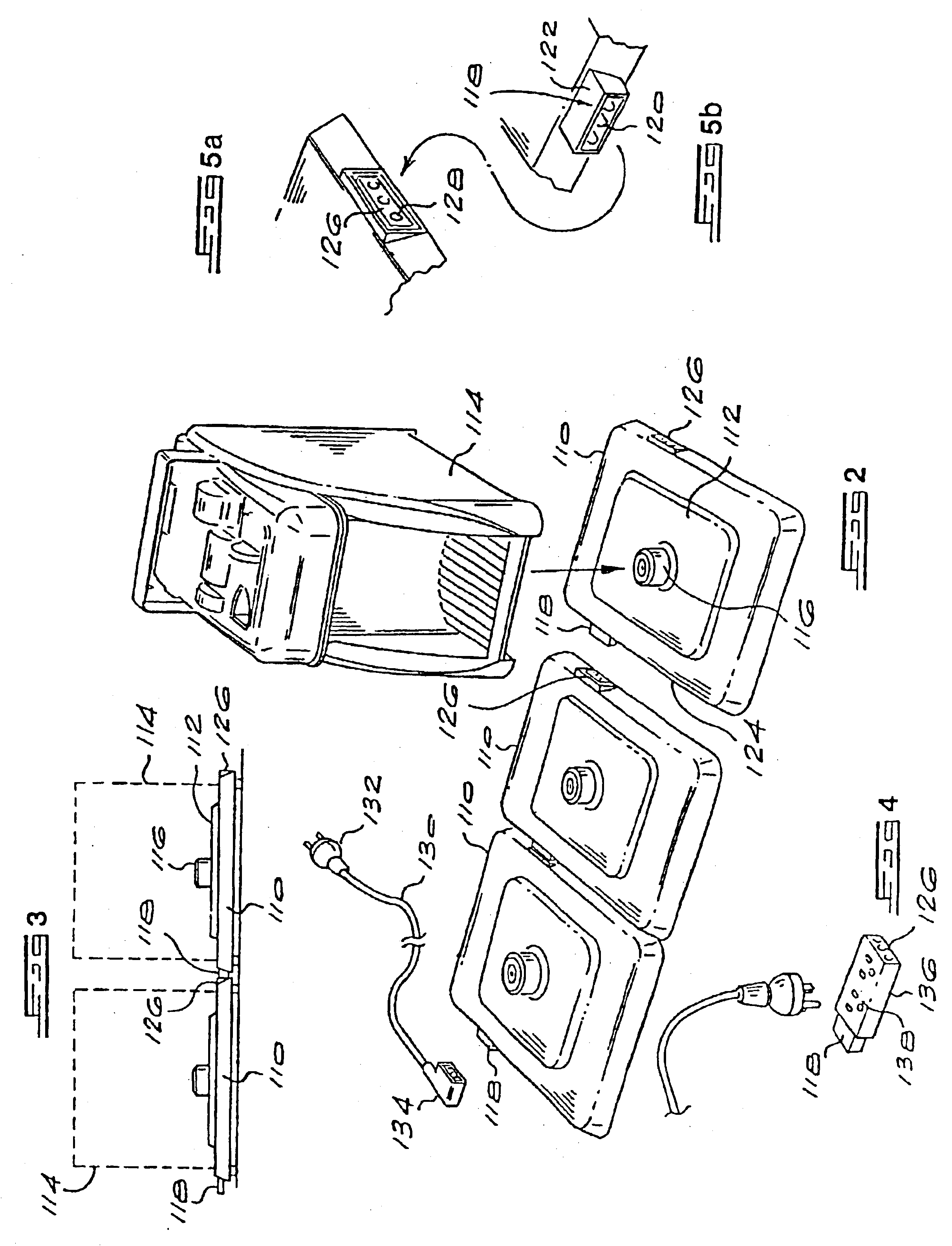
A modular appliance system comprises several similarly shaped modular appliances such as kettles, toasters and the like, and a modular base system with cordless connectors on which the appliances can be placed. In one embodiment, the base is larger than the base of an individual appliance, and accommodates two or more appliances side by side. In another embodiment, the base comprises individual base units which can be connected together electrically to create a composite base unit which accommodates the required number of appliances.

Description

BACKGROUND OF THE INVENTIONThis invention relates to a modular appliance system.Modern homes tend to be relatively compact and space is usually at a premium in working areas such as kitchens. At the same time, the number of appliances available is increasing and an average home owner will typically have at least a kettle, a toaster, a coffee maker and one or more other counter-top appliances in his or her kitchen. This leads to crowding and clutter in the kitchen.It is an object of the invention to address this phenomenon.SUMMARY OF THE INVENTIONAccording to the first aspect of the invention there is provided a modular appliance system comprising:a plurality of modular appliances; anda base unit for supporting at least two of the modular appliances simultaneously, the base unit having at least two electrical connectors adapted for engagement with complemental connectors on respective appliances, thereby to connect the appliances to an electrical source via the base unit.According to...

Claims


Application Information

Patent Timeline
Patent Type & Authority Patents(United States)
IPC IPC(8): A47J37/08A47J27/21A47J37/06H01R25/00
CPCA47J27/2105A47J37/08A47J37/0611H01R25/006
Inventor KHOURY, EDWARD JOSEPH
Owner SEEFF STANLEY JOSEPH
Learn More