Eureka AIR delivers breakthrough ideas for toughest innovation challenges, trusted by R&D personnel around the world.

Urological resectoscope for children

a resectoscope and urology technology, applied in the field of urological resectoscopes for children, can solve the problems of drawbacks arising from substantial added costs

Inactive Publication Date: 2005-03-01
OLYMPUS WINTER & IBE
View PDF3 Cites 11 Cited by
  • Summary
  • Abstract
  • Description
  • Claims
  • Application Information

AI Technical Summary

Benefits of technology

An objective of the present invention is to create a resectoscope of the above species for which the costs of employing the two surgical procedures shall be reduced.
In further accordance with the present invention, the guide tube assures secure guidance of the drive rod to the optic tube within the free space in the main casing and as a result lateral, undesired motions are precluded. Illustratively, this guide tube may be in addition to another one, which, in apparatus of the state of the art, does guide the drive rod in the stem zone on the optic tube.
In further accordance with the present invention, design of the deviation site is especially compact because—besides the very thin-walled guide tube at the deviation site—elements of the drive rod are present only in the two angular positions. Any additional intermediate zone of the drive rod, which would be pivoted about the optic tube and which would entail additional bulk, is thereby eliminated.

Problems solved by technology

Because the full resectoscope must be manufactured in two designs, the substantial added costs entail a drawback.

Method used


Image

  • Urological resectoscope for children
  • Urological resectoscope for children
  • Urological resectoscope for children

Examples


Embodiment Construction

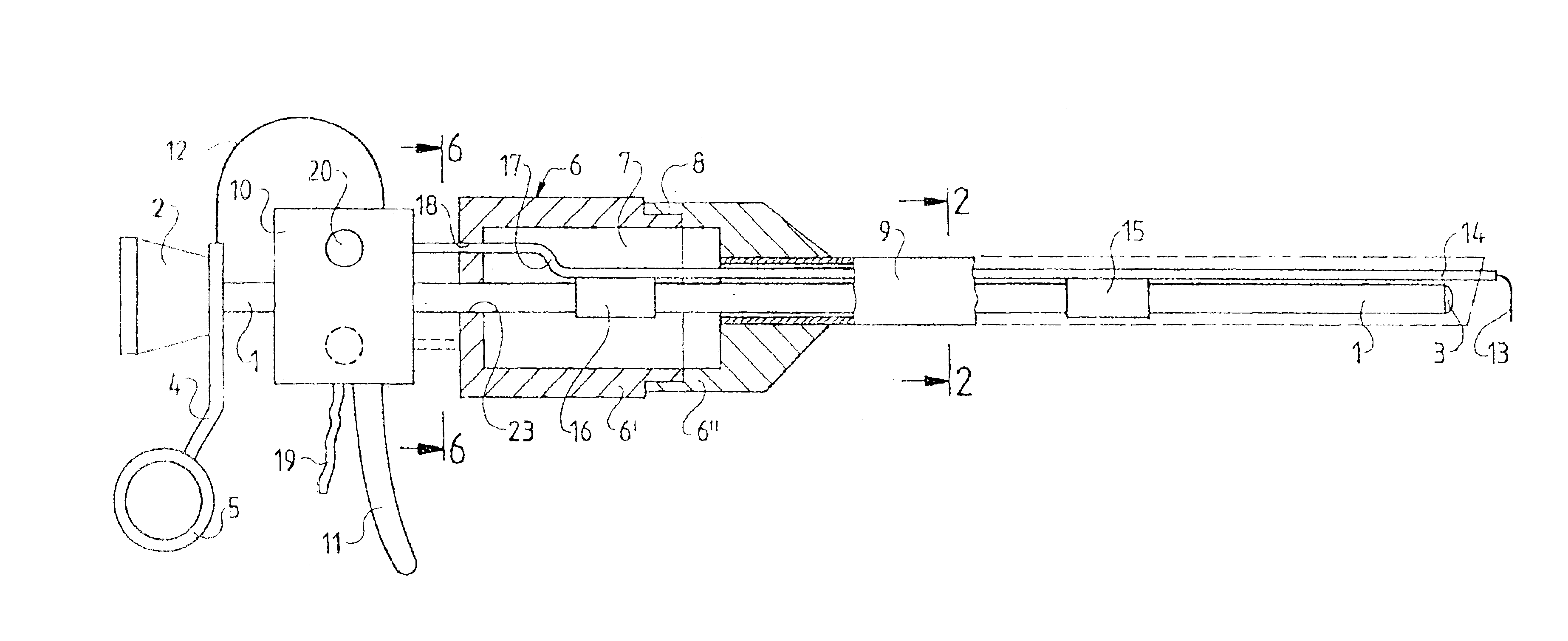
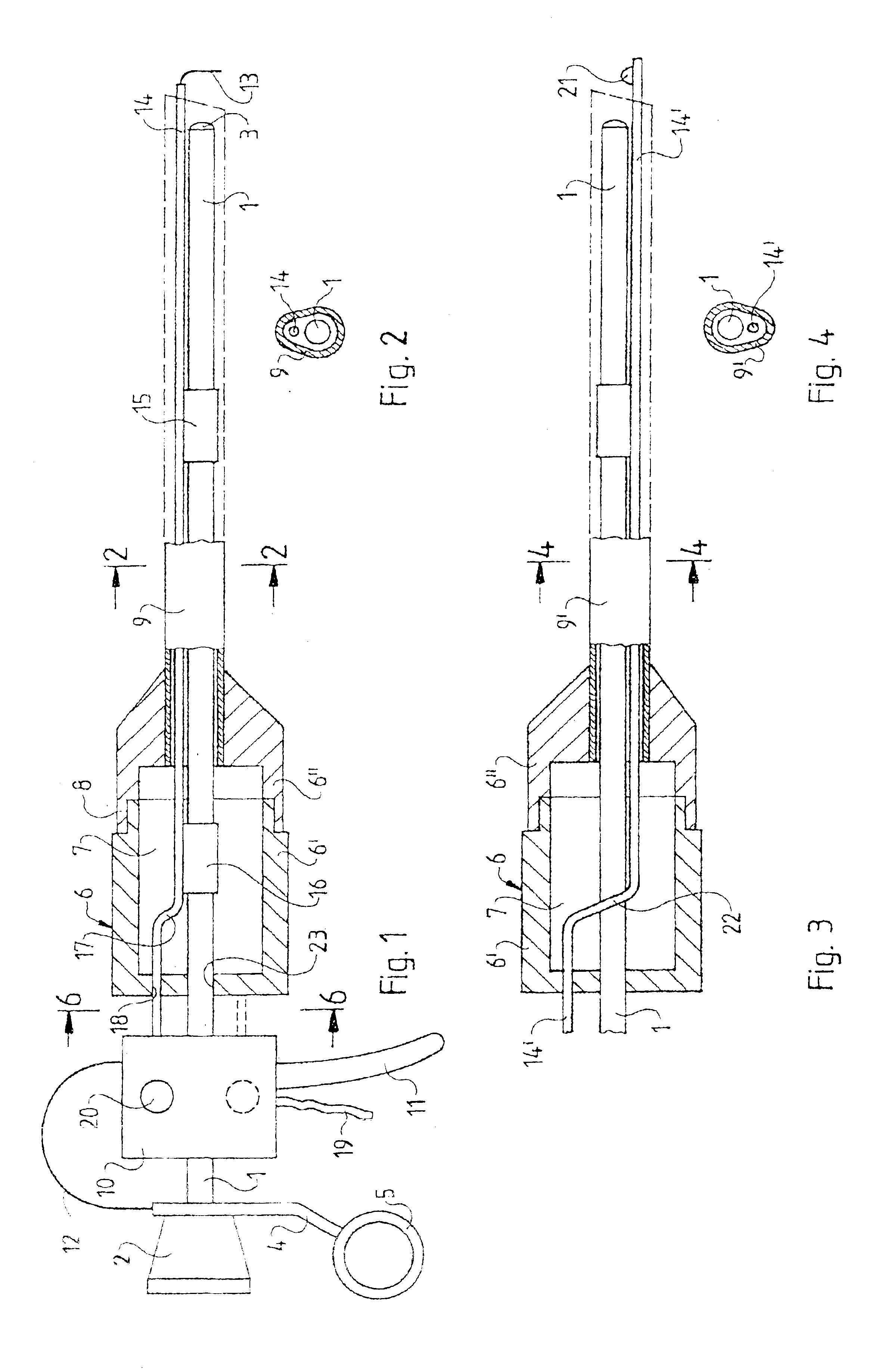
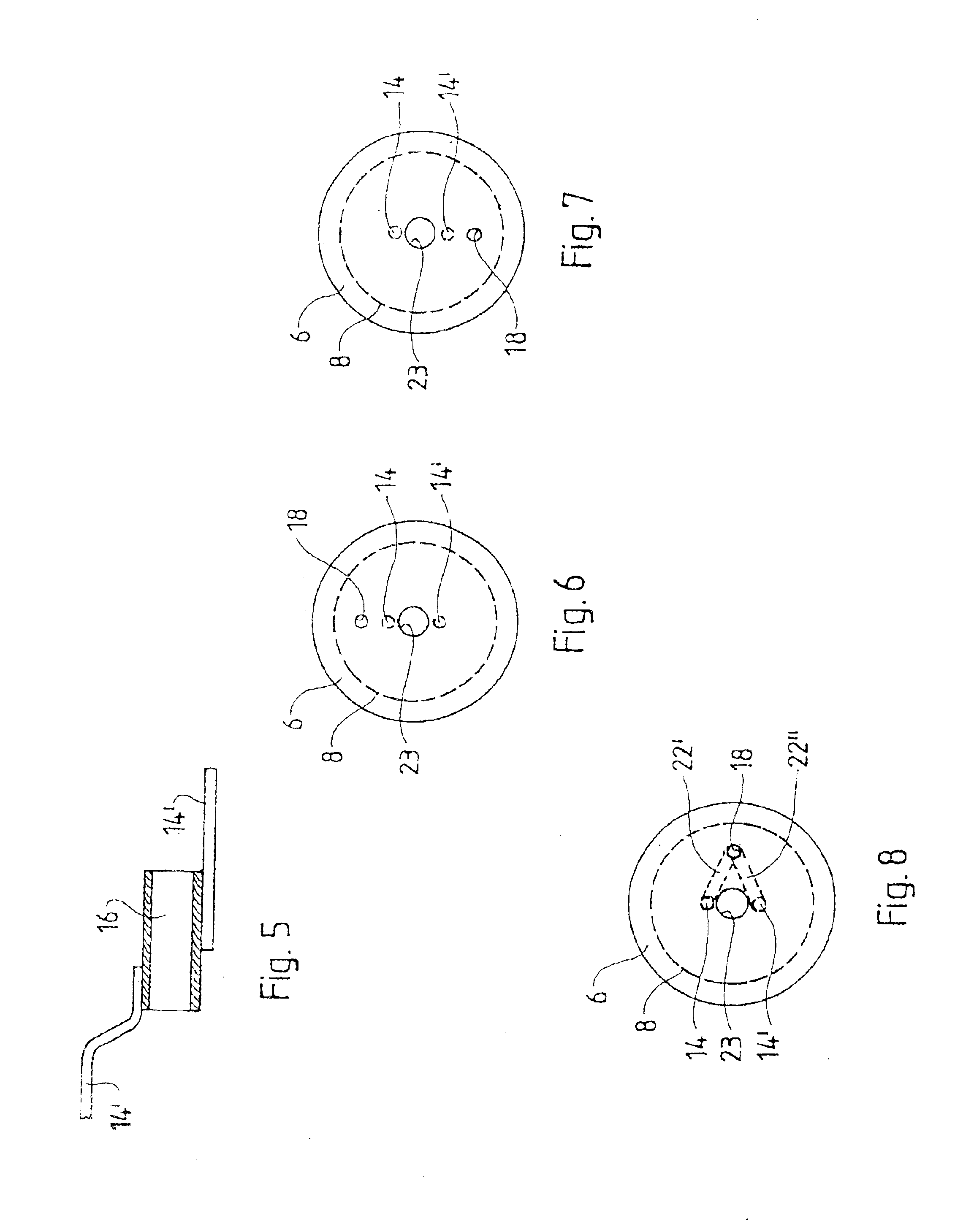
FIG. 1 is a partly sectional view of a resectoscope of the invention. An optic tube 1 receives in removable manner,(for instance for cleaning purposes), an optics with a proximal ocular 2 and a distal objective 3. An optics guiding plate 4 fitted at its bottom with a thumb ring 5 is affixed at the proximal end of the optics tube 1.

A main casing 6 is affixed on the optics tube a distance from the optics guiding plate 4 and subtends a free space 7 around this optics tube 1. In the embodiment shown, the main casing 6 is a hollow housing.

A stem tube 9 shown mostly in dashed lines is detachably affixed on a flange 8 at the distal end of the main casing 6.

In the embodiment shown in FIGS. 1 and 3, the casing 6 consists of two parts 6′, 6″ that may be joined to each other at the flange 8. The proximal part 6′ of the main casing is affixed to the optics tube 1. The detachable, distal part 6″ is affixed to the stem tube 9 and constitutes the stem tube's coupling for connection to the main cas...


PUM


Abstract

A urological resectoscope includes a main casing and an optic guide plate mounted proximally to and a fixed distance from the main casing. A slider is displaceably guided between the main casing and the optic guide plate. A drive rod is detachably affixed to the slider at a first distance from an optic tube longitudinally passing through the resectoscope and in a first angular position to the grip, said rod running from the slider, parallel to the optic tube, through the main casing and then in a second angular position relative to the optic tube and at a second, minute distance from it, and the optic tube together with matched, tightly enclosing stem tube of matched cross-section running as far as said stem tube's distal end zone, the drive rod supporting a surgical implement, characterized in that a free space corresponding at least to the excursion of the drive rod is provided in the main casing and is fitted in the region of the free space with a deviation site where it is pivoted out of the first angular position and first distance from said optic tube into the second angular position and the second distance.

Description

BACKGROUND OF THE INVENTION1. Field of the InventionThe present invention relates to a urological resectoscope and, more specifically, toward urological resectoscopes for children.2. Description of Related ArtSuch resectoscopes require being fitted with an especially narrow stem tube so they may be used in the still very narrow juvenile urethra. Accordingly, the stem tube encloses, by its almost pear-like, shape-matched cross-section, the cross-sections of the drive rod and of the optic tube. To minimize the cross-sections, the otherwise conventional double-tube design used in resectoscopes to create a second rinsing duct is eliminated.A children's resectoscope of this kind is known from the applicant's catalog TRANSURETHRALE RESEKTION, pp 30-32, 1997. Catalog # A3753 on page 32 relates to and shows a surgical insert of which the surgical implement is a cutting loop. With respect to the grip situated below the operational direction, the cutting loop must be affixed above and, accord...

Claims


Application Information

Patent Timeline
IPC IPC(8): A61B18/14A61B18/00
CPCA61B18/149A61B2018/00982A61B2018/00601A61B2018/00505
Inventor WOSNITZA, THOMASDICKOPP, JORG
Owner OLYMPUS WINTER & IBE
Why Eureka
Eureka Blog
Learn More