Suspension device having anti-roll compensation

a suspension device and anti-roll technology, applied in the direction of roofs, transportation and packaging, tractors, etc., can solve the problems of driver's cab inevitably following, driver's cab tilting to the same extent as the vehicle chassis, or even mor

Inactive Publication Date: 2013-05-07
ZF FRIEDRICHSHAFEN AG
View PDF23 Cites 6 Cited by
  • Summary
  • Abstract
  • Description
  • Claims
  • Application Information

AI Technical Summary

Benefits of technology

[0010]Proceeding from this background, the problem addressed by the present invention is that of creating a suspension device for resiliently suspending a mass relative to a substructure, in particular for suspending a driver's cab in a truck, with which the stated disadvantages of the prior art can be overcome. In particular, the suspension device should prevent or compensate for undesired rolling motions of the mass or driver's cab, including roll-inducing motions or tilted positions of the substructure or chassis.

Problems solved by technology

However, this also causes the driver's cab to inevitably follow every roll-inducing motion coming from the chassis.
Cornering or driving on an incline, or over irregularities present on only one side of the road, can cause the driver's cab to tilt to the same extent as the vehicle chassis, or even more.

Method used


Image

  • Suspension device having anti-roll compensation
  • Suspension device having anti-roll compensation
  • Suspension device having anti-roll compensation

Examples


Embodiment Construction

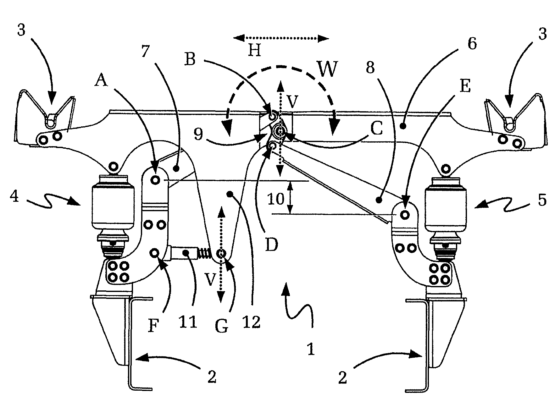
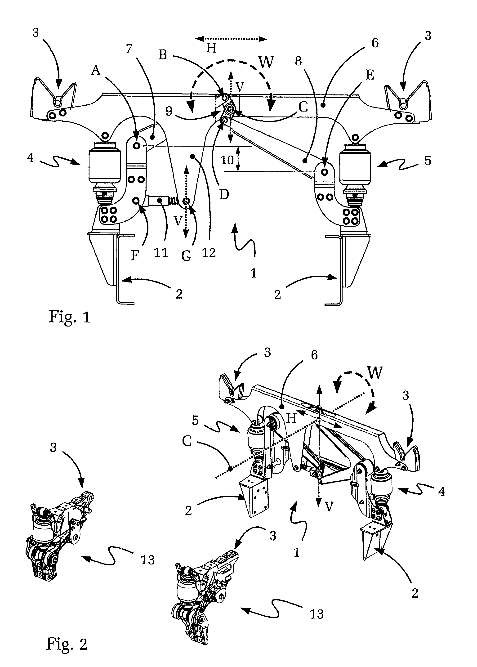
[0044]FIG. 1 shows, in a schematic depiction, one embodiment of a suspension device 1 according to the present invention. The suspension device 1 is used to support a truck driver's cab (not depicted) in the region of the rear end of the driver's cab, relative to the chassis 2 of the truck indicated schematically in FIG. 1. The suspension device 1 according to FIG. 1 is equipped with two mounting points 3 for mounting and supporting the driver's cab.

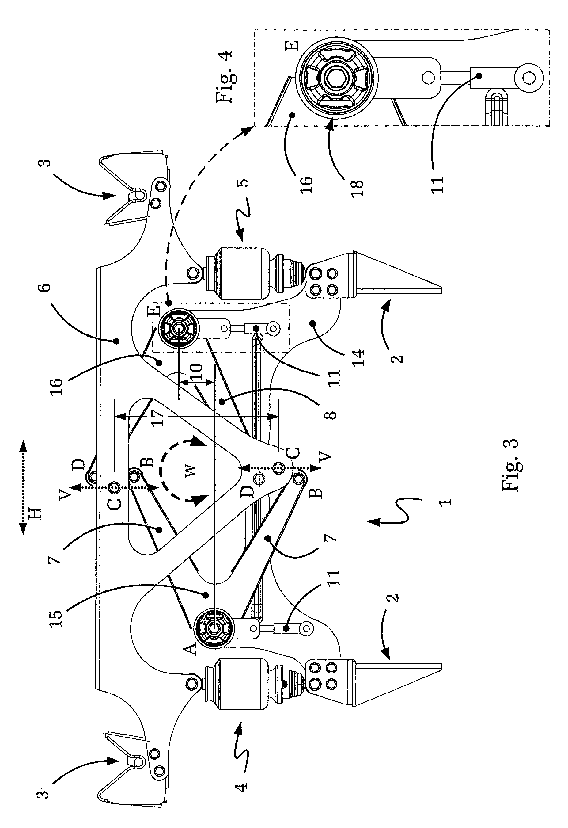
[0045]FIG. 1 also shows that the suspension device 1 disposed between the driver's cab and the chassis 2 comprises two spring / damper devices 4, 5 and a Watt's linkage having five joints labeled with the letters A, B, C, D, E. Of the joints A to E, in the case of the embodiment shown, A and E are attached to the chassis, while C is attached to the driver's cab or is connected to the upper cross-bridge 6 of the suspension device 1. The pivot points A to E of the Watt's linkage are interconnected by an arrangement composed of two lateral th...


PUM


Abstract

A suspension device for suspending a mass relative to a substructure. The suspension device comprises a spring / damper arrangement which is disposed between the mass and the substructure and dampens vibrations, and comprises at least one Watt's linkage. At least one of the pivot points of the Watt's linkage is movably connected to the mass and the substructure. The relative position between the pivot point, the mass and the substructure can be adjusted by at least one substantially linearly acting actuator. The suspension device is robust and suitable for determining the vertical degree of freedom of movement of a truck driver's cab, and for damping or preventing undesired movement of the driver's cab. At the same time, undesired rolling or tilting motion of the driver's cab can be actively controlled or prevented by using the actuators.

Description

[0001]This application is a National Stage completion of PCT / DE2009 / 050074 filed Dec. 17, 2009, which claims priority from German patent application serial no. 10 2008 063 812.9 filed Dec. 19, 2008.FIELD OF THE INVENTION[0002]The invention relates to a suspension device for the resilient and impact-damping suspension of a mass, such as a truck driver's.BACKGROUND OF THE INVENTION[0003]Suspension devices of the initially described type can be used, for example, although certainly not exclusively, in trucks, agricultural vehicles, or heavy-duty vehicles to decouple the driver's cab from the vehicle chassis, with respect to vibrations and motions, to the greatest extent possible.[0004]Since high spring and damping rates must be selected for the spring / damper units of the chassis in heavy-duty vehicles due to considerable vehicle weights and large unsprung masses in the chassis, road irregularities or vibrations originating in axles and the drive train are still often transferred, to a ...

Claims


Application Information

Patent Timeline
Patent Type & Authority Patents(United States)
IPC IPC(8): B62D33/06B62D33/10B60G17/016
CPCB60G99/008B62D33/0608B60G2200/342B60G2202/413B60G2204/421B60G2202/314
Inventor BUHL, MANFREDQUAING, MATTHIASLANGHORST, FRIEDHELMLORENZ, KARLLAHMANN, KERSTINEISMANN, JENS
Owner ZF FRIEDRICHSHAFEN AG
Why Eureka
Try Eureka